Heat pump system

a heat pump and heat exchange technology, applied in heat pumps, heating types, lighting and heating apparatuses, etc., can solve the problems of poor energy efficiency of the unit and diminished comfort, and achieve the effect of preventing the rise of excessive temperature of the aqueous medium more reliably

Inactive Publication Date: 2011-12-15
DAIKIN IND LTD +1
View PDF7 Cites 18 Cited by
  • Summary
  • Abstract
  • Description
  • Claims
  • Application Information

AI Technical Summary

Benefits of technology

[0014]According to the aspect described above, because in a case where an air temperature differential between a detected air temperature detected by the air-temperature-detecting means and a set air temperature set by the air-temperature-setting means is greater than a predetermined third target temperature differential, the second target temperature differential is modified in the direction of a smaller medium temperature differential, flow rate control of the aqueous medium can take place in coordination with room temperature, and excessive temperature rise of the aqueous medium can be more reliably prevented, even in cases of decreased load on the usage-side heat exchanger.

Problems solved by technology

However, a problem with such conventional hydronic heating devices of a heat pump type is that in a case of a decrease in load on the air-warming floor panel or air-warming heat exchanger which warms the room, the outlet / inlet temperature differential of the water / refrigerant heat exchanger becomes smaller, resulting in an excessive temperature rise of the water being supplied to the air-warming floor panel or air-warming heat exchanger, possibly leading to auto-shutoff or poor energy efficiency of the unit, as well as to diminished comfort.

Method used


Image

  • Heat pump system
  • Heat pump system
  • Heat pump system

Examples


embodiment

Overall Configuration

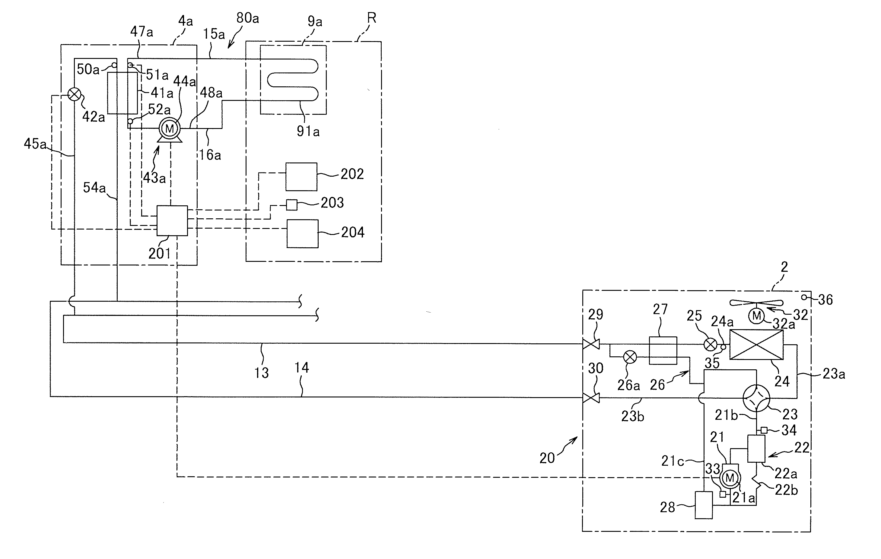
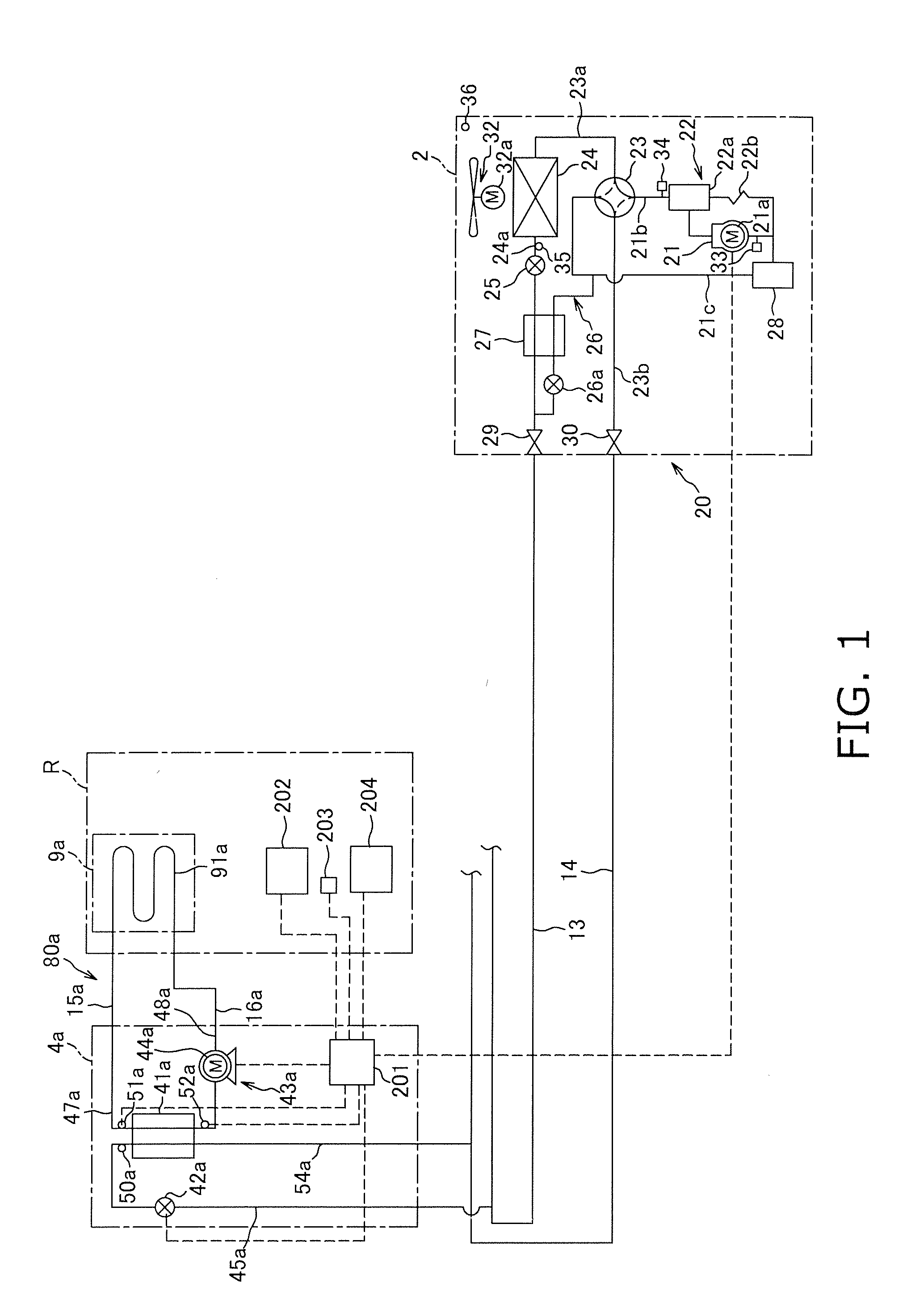
[0019]FIG. 1 is a view showing the general configuration of a heat pump system 1 according to an embodiment of the present invention. A heat pump system 1 is a device capable of utilizing a vapor compression type heat pump cycle to carry out an operation to heat an aqueous medium.

[0020]The heat pump system 1 is primarily provided with a heat source unit 2, a usage unit 4a, a liquid refrigerant communication tube 13, a gas refrigerant communication tube 14, a hot-water air-warming unit 9a, an aqueous medium communication tube 15a, and an aqueous medium communication tube 16a. The heat source unit 2 and the usage unit 4a are connected via the refrigerant communication tubes 13, 14, and thereby constitute a heat-source-side refrigerant circuit 20, while the usage unit 4a and the hot-water air-warming unit 9a are connected via the aqueous medium communication tubes 15a, 16a, and thereby constitute an aqueous medium circuit 80a. HFC-410A, which is a type of HFC-based...

modified examples

(A)

[0110]In the aforedescribed embodiment, in order to aid in understanding of the invention, an example of a single usage unit 4a furnished on the usage side was depicted as one example of the heat pump system 1 of the present invention, but the present invention is not limited thereto, and it is possible for another usage unit (an indoor air conditioning unit or the like) to be connected in parallel with the usage unit 4a to the liquid refrigerant communication tube 13 and the gas refrigerant communication tube 14. In this case as well, by carrying out the operation control of the aforedescribed embodiment, excessive temperature rise of the aqueous medium can be reliably prevented, even in a case of a decrease in load on the usage-side heat exchanger 41a.


PUM


Abstract

A heat pump system includes a refrigerant circuit, an inlet temperature sensor measuring a heat exchanger inlet temperature of an aqueous medium in a usage-side heat exchanger of the refrigerant circuit, an outlet temperature sensor measuring a heat exchanger outlet temperature of the aqueous medium in the usage-side heat exchanger, a variable-capacity circulating pump circulating the aqueous medium inside a hot-water circuit of a loop, and a controller. The controller controls refrigerant-side circulation rate in the refrigerant circuit to bring a temperature of the aqueous medium at the outlet of the usage-side heat exchanger to a targeted first target temperature, and operating capacity of the circulating pump to bring a medium temperature differential of the aqueous medium between the outlet and the inlet of the usage-side heat exchanger to a targeted second target temperature differential.

Description

TECHNICAL FIELD[0001]The present invention relates to a heat pump system for circulating an aqueous medium.BACKGROUND ART[0002]Hydronic heating devices of a heat pump type like that disclosed in Patent Citation 1 (Japanese Laid-open Patent Application 2003-314838) are known in the prior art. This hydronic heating device is provided with an outdoor unit of a heat pump type; a water / refrigerant heat exchanger for bringing about heat exchange between a refrigerant and water; an air-warming floor panel or air-warming heat exchanger connected to the water / refrigerant heat exchanger by a hot-water tube; and a circulating pump for circulating hot water through the hot-water tube.SUMMARY OF THE INVENTION[0003]However, a problem with such conventional hydronic heating devices of a heat pump type is that in a case of a decrease in load on the air-warming floor panel or air-warming heat exchanger which warms the room, the outlet / inlet temperature differential of the water / refrigerant heat exch...

Claims


Application Information

Patent Timeline
Patent Type & Authority Applications(United States)
IPC IPC(8): F25B30/00
CPCF24D3/02Y02B30/745F24D19/1012F24D2200/12F25B13/00F25B2313/003F25B2313/02741F25B2313/0314F25B2313/0315F25B2339/047F25B2600/13F25B2700/1931F25B2700/1933F25B2700/2104F25B2700/2106F25B2700/21162F25B2700/21163Y02B30/12F24D3/18Y02B30/70F25B49/02F25B30/02F24D3/00F24H15/254F24H15/174F24H15/231F24H15/31F24H15/38F24H15/232F24H15/156F24H15/385F24H15/242F24H15/176F24H15/258
Inventor HONDA, MASAHIRO
Owner DAIKIN IND LTD
Why Eureka
Try Eureka