Air conditioning system for motor vehicles

a technology for air conditioning systems and motor vehicles, which is applied in the direction of vehicle maintenance, vehicle cleaning, transportation and packaging, etc., can solve the problems of cold air being supplied, cold air being fed, and cold air being mixed

Inactive Publication Date: 2013-09-05
HANON SYST
View PDF21 Cites 13 Cited by
  • Summary
  • Abstract
  • Description
  • Claims
  • Application Information

AI Technical Summary

Benefits of technology

[0020]With the air conditioning system according to the present invention, a part of the cold air flowing through the cold air path is introduced into the defrost vent when the warm air flowing through the warm air path is bypassed toward the defrost vent. Unlike the conventional air conditioning system in which only the warm air is bypassed toward the defrost vent, the air conditioning system of the present invention can provide an

Problems solved by technology

The conventional air conditioning system referred to above has a drawback in that the mixing efficiency of the cold air and the warm air in the air mixing area A becomes lower due to the difference in wind velocity and air density between the cold air flowing through the cold air path 14 and the warm air flowing through the warm air path 16.
This poses a problem in that the cold air and the warm air flow in an unmixed laminar state.
This poses a problem in that a large amount of cold air is introduced into the defrost vent 20 existing near the vehicle window and a large amount of warm air is admitted into the floor vent 22 existing near the vehicle floor.
Thus, there is a disadvantage that a large amount of cold air is supplied to the upper region of the vehi

Method used


Image

  • Air conditioning system for motor vehicles
  • Air conditioning system for motor vehicles
  • Air conditioning system for motor vehicles

Examples


first embodiment

[0035]Prior to describing the features of an air conditioning system for motor vehicles according to the present invention, the general configuration of the air conditioning system will be briefly described with reference to FIG. 4.

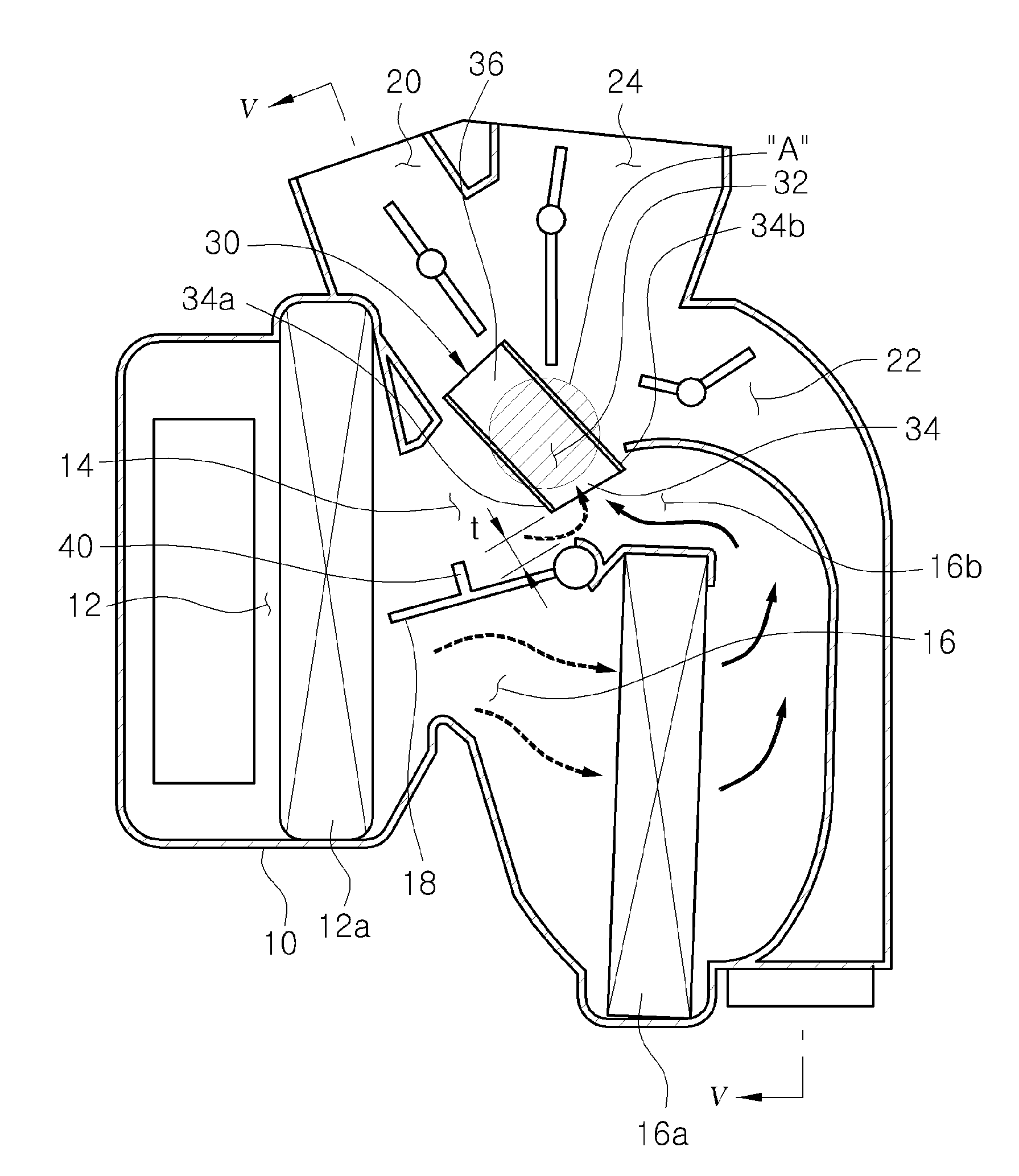
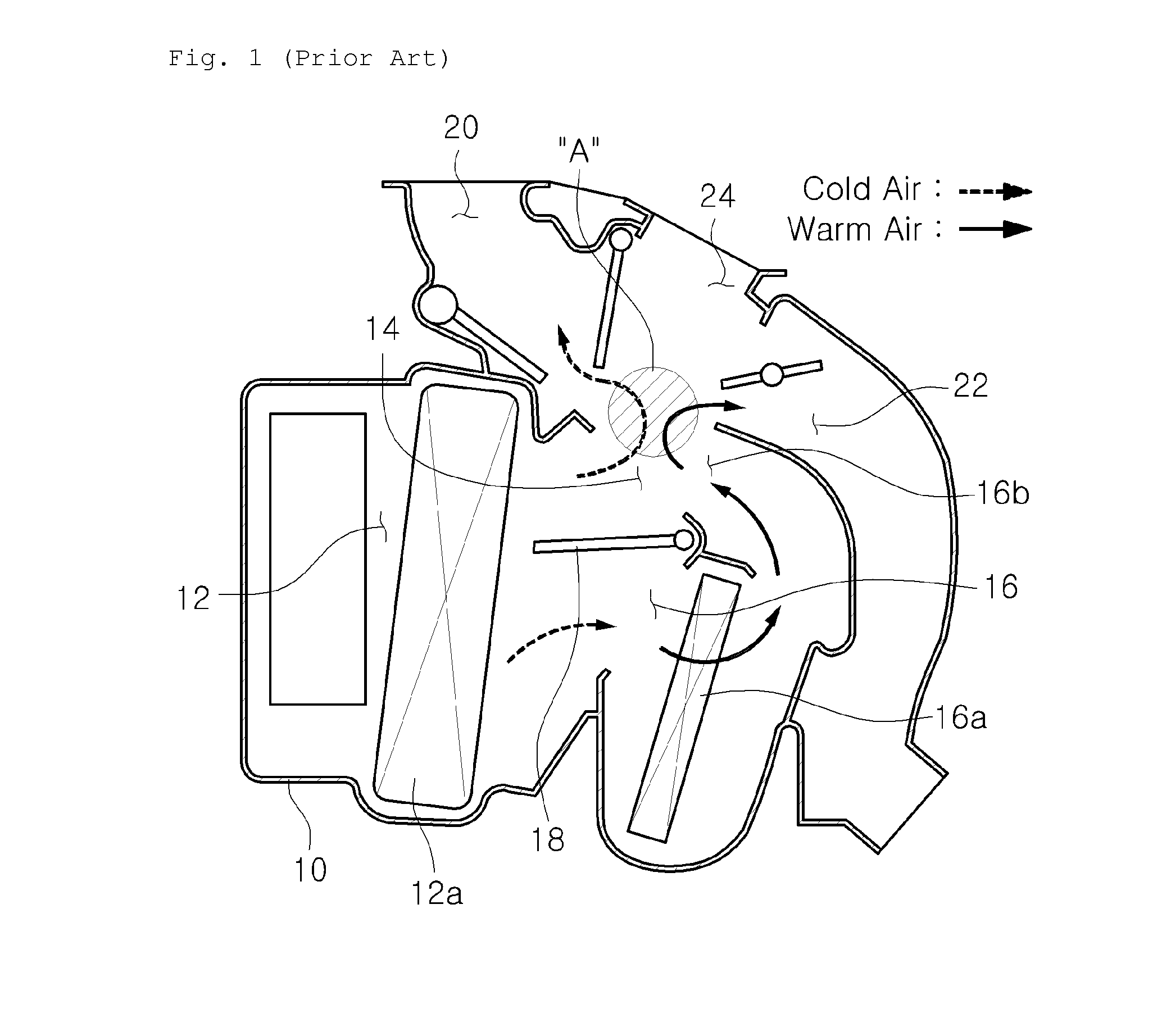
[0036]The present air conditioning system includes an air conditioner case 10 within which a main flow path 12 is formed. An evaporator 12a is installed within the main flow path 12. The evaporator 12a serves to cool the air flowing along the main flow path 12.

[0037]The main flow path 12 is bifurcated into a cold air path 14 and a warm air path 16. A heater core 16a is installed within the warm air path 16. A temperature control door 18 is arranged at a bifurcating point of the cold air path 14 and the warm air path 16. The cold air cooled by the evaporator 12a passes through the cold air path 14. The warm air heated by the heater core 16a passes through the warm air path 16.

[0038]The temperature control door 18 is swung between the cold air path 14 and t...

second embodiment

[0061]FIG. 9 shows an air conditioning system according to a second embodiment of the present invention. The air conditioning system of the second embodiment includes a cold air introducing cutout portion 50 formed in the outlet 36 of the bypass duct 30. The cold air introducing cutout portion 50 is formed by partially cutting away the outlet 36 of the bypass duct 30 and is arranged in an opposing relationship with the cold air path 14. In the present embodiment, the cold air introducing cutout portion 50 serves as a cold air introducing means.

[0062]A part of the cold air flowing through the cold air path 14 is introduced into the bypass duct 30 through the cold air introducing cutout portion 50. The cold air thus introduced is mixed with the bypassed warm air flowing through the bypass duct 30, thereby reducing the temperature of the bypassed warm air flowing through the bypass duct 30. As a result, it is possible to effectively reduce the temperature of the warm air flowing toward...

third embodiment

[0070]FIG. 12 shows an air conditioning system according to a third embodiment of the present invention. The air conditioning system of the third embodiment includes a branch duct 70 branched from the bypass duct 30. The branch duct 70 is branched from the bypass duct 30 to face toward a face vent 24.

[0071]The branch duct 70 serves to bypass the air flowing through the bypass duct 30 toward the face vent 24. Thus, a mixture of the warm air and the cold air is also supplied to an intermediate region of the vehicle room existing between the upper region and the lower region.

[0072]As a result, the intermediate region of the vehicle room is kept at a temperature similar to the temperature of the upper and lower regions of the vehicle room. This makes it possible to minimize the temperature deviation generated between the upper and lower regions and the intermediate region of the vehicle room, consequently enhancing the pleasantness within the vehicle room.


PUM


Abstract

An air conditioning system for motor vehicles includes an air conditioner case, a cold air path through which a cold air flows, a warm air path through which a warm air flows, a temperature control door arranged to swing between the cold air path and the warm air path so as to control an opening degree of the cold air path and an opening degree of the warm air path, a defrost vent arranged to discharge the cold air and the warm air toward an upper region of a vehicle room, a bypass duct arranged to bypass a part of the warm air toward the defrost vent, the bypass duct including an inlet aligned with the warm air path and an outlet aligned with the defrost vent, and a cold air introducing portion arranged in at least one of the inlet and the outlet of the bypass duct.

Description

FIELD OF THE INVENTION[0001]The present invention relates to an air conditioning system for motor vehicles and, more particularly, to an air conditioning system for motor vehicles in which a warm air flowing through a warm air path is bypassed toward a defrost vent such that a cold air flowing through a cold air path can be partially admitted into a vehicle room during the process of increasing the temperature of the upper region of the vehicle room, thereby preventing a phenomenon that the temperature of the upper region of the vehicle room grows too high and a phenomenon that the vehicle room environment becomes unpleasant.BACKGROUND OF THE INVENTION[0002]A motor vehicle is provided with an air conditioning system for cooling or warming a vehicle room. As shown in FIG. 1, an air conditioning system includes an air conditioner case 10 within which a main flow path 12 is formed. An indoor air or an outdoor air fed from a blower (not shown) flows through the main flow path 12. An eva...

Claims


Application Information

Patent Timeline
IPC IPC(8): B60H1/00B60H1/24B60J1/00
CPCB60H1/00064B60H1/247B60H2001/00164B60H2001/00092B60J1/002B60H2001/00721B60H1/00678
Inventor KIM, DOO HOONHAN, JOONG MANLEE, JUN KANGPARK, SANG KYUHAN, YOUNG HUMNAM, SOO BYEONG
Owner HANON SYST
Why Eureka
Try Eureka