Small wave-guide radiators for closely spaced feeds on multi-beam antennas

a multi-beam antenna and waveguide technology, applied in waveguide horns, antennas, electrical equipment, etc., can solve the problems of increasing cost and complexity, requiring relatively small spacing between satellites, and reducing performance, so as to reduce size, eliminate bore sight errors, and sacrifice antenna gain and noise temperature

Inactive Publication Date: 2007-05-29
PRO BRAND INT
View PDF11 Cites 228 Cited by
  • Summary
  • Abstract
  • Description
  • Claims
  • Application Information

AI Technical Summary

Benefits of technology

[0008]Other systems introduce dielectric material into the DBS feed(s) in order to reduce size. These dielectric feeds can generally be made small enough to allow the feeds to be placed at the correct location (separation) to eliminate bore sight errors but dielectric material introduces loss sacrificing antenna gain and noise temperature. Cost and manufacturing complexity is also generally increased with the addition of a dielectric material. In addition many implementations extend the dielectric material well beyond the circular wave-guide in order to improve the feeds directivity and match. The phase center of such a feed is usually somewhere between the end of the dielectric and the metal wave-guide. This can pose a problem to the adjacent feeds if a portion of the dielectric feed partially blocks the path the adjacent feed(s). FIGS. 4a,b show how dielectric shrinks the circular feed diameter providing more space between the feeds. It also shows how the dielectric sticks out in front of the feeds causing blockage of energy into the adjacent feeds at some angles of incidence.
[0009]Increasing the focal length (or f / d=focal length to diameter ratio) is another technique commonly used to increase the feed spacing required for a given satellite spacing. However increasing the focal length makes the feed support arm longer increasing cost and / or degrading mechanical stability. In addition for longer focal length antenna's feeds must be either larger (increasing cost) or gain, noise temperature and pattern performance will degrade due to excessive spill over (energy spillover the reflector due to inadequately directive feeds).
[0011]The invention provides a solution to the problems discussed above by using wave guide structures that are narrower than circular wave guide structures particularly in the direction that allows additional feeds to be placed very closely in order to reduce or eliminate bore sight errors without the introduction of dielectric material and without substantial increases in focal length. So this invention immediately minimizes cost and improves performance by eliminating dielectric losses and keeping the feed support arm short. In addition this invention has several possible embodiments most of which are easily manufactured in high volume because they can be integrated directly into the LNBF die-cast housing. Furthermore for circular polarity most of the embodiments of this invention allow a CP polarizer to also be integrated directly into the housing. This invention has obvious advantages on single reflector systems but could also be used in dual reflector systems where feed spacing is still a concern.

Problems solved by technology

In cases where the satellites are very close this creates a challenge for reflector antenna systems often resulting in compromised performance and / or increased cost and complexity.
The difficulty arises because relatively small spacing between satellites requires relatively small spacing between feeds.
These small feed spacing limits the size of the feed and other parameters making it difficult to achieve good of even adequate antenna performance and cost.
Some systems using modestly sized feeds limit how close the feeds can be placed such that the feeds are farther apart than the ideal feed separation resulting in wider than ideal angular separation between the antenna beams associated with each feed.
This results in an angular bore sight errors on one or more of the beams. FIG. 2 shows this error and resulting loss in power.
Although fairly small there are still inherent limits on how small these circular wave-guide feeds can be made and correspondingly how close adjacent feeds can be placed.
This in turn can cause the bore-sight errors and performance degradations discussed above. FIGS. 3a,b show a typical situation where circular radiators are used next to elliptical or rectangular feed(s).
In this example very little space is available between the feeds.
Cost and manufacturing complexity is also generally increased with the addition of a dielectric material.
This can pose a problem to the adjacent feeds if a portion of the dielectric feed partially blocks the path the adjacent feed(s). FIGS. 4a,b show how dielectric shrinks the circular feed diameter providing more space between the feeds.
However increasing the focal length makes the feed support arm longer increasing cost and / or degrading mechanical stability.
In addition for longer focal length antenna's feeds must be either larger (increasing cost) or gain, noise temperature and pattern performance will degrade due to excessive spill over (energy spillover the reflector due to inadequately directive feeds).
Dual reflector systems can be used to increase feed spacing and improve performance but these systems generally increase cost and complexity.

Method used


Image

  • Small wave-guide radiators for closely spaced feeds on multi-beam antennas
  • Small wave-guide radiators for closely spaced feeds on multi-beam antennas
  • Small wave-guide radiators for closely spaced feeds on multi-beam antennas

Examples


Embodiment Construction

[0028]The embodiments of the present invention meet the challenge of designing and manufacturing a single antenna with multiple closely spaced feed horns for simultaneous reception from (and / or transmission to) multiple satellites that are closely spaced from the perspective of the antenna. The feed horns and associated circular polarity antenna systems for multiple-beam, multi-band antennas are designed to achieve good circular polarity performance over broad and multiple frequency bands.

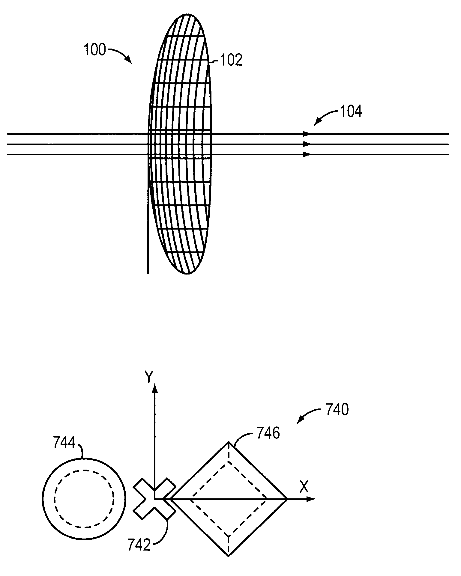
[0029]In general, elliptically and other shaped horn apertures are described in the examples in this disclosure, however this invention can be applied to any device that introduces phase differentials between orthogonal linear components that needs to be compensated for in order to achieve good CP conversion and cross polarization (Cross polarization) isolation including but not limited to any non-circular beam feed, rectangular feeds, oblong feeds, contoured corrugated feeds, feed radomes, specifi...


PUM


Abstract

A relatively low cost, easy to install and aesthetically pleasing digital video broadcast from satellite (DVBS) elliptical horn antenna designed to receive satellite television broadcast signals with circular polarity. This type antenna may be implemented as a multi-beam, multi-band antenna with closely spaced antenna feed horns operable for simultaneously receiving signals from multiple satellites that are closely spaced from the perspective of the antenna.

Description

REFERENCE TO RELATED APPLICATIONS[0001]This application claims priority to commonly-owned copending U.S. Provisional Patent Application Ser. No. 60 / 572,080 entitled “Small Wave-Guide Radiators For Closely Spaced Feeds on Multi-Beam Antennas” filed May 18, 2004, which is incorporated herein by reference; and U.S. Provisional Patent Application Ser. No. 60 / 571,988 entitled “Circular Polarization Technique for Elliptical Horn Antennas” filed May 18, 2004, which is also incorporated herein by reference.TECHNICAL FIELD[0002]The present invention is generally related to antenna systems designed to receive broadcast signals with circular polarity and, more particularly, is directed to digital video broadcast satellite (DVBS) antenna systems.SUMMARY OF THE INVENTION[0003]An increasing number of applications are requiring systems that employ a single antenna designed to receive from and / or transmit to multiple sources simultaneously (multiple satellites in particular). In cases where the sat...

Claims


Application Information

Patent Timeline
Patent Type & Authority Patents(United States)
IPC IPC(8): H01Q13/00H01Q13/02H01Q19/17H01Q25/00
CPCH01Q13/0225H01Q19/17H01Q25/007
Inventor COOK, SCOTT J.
Owner PRO BRAND INT
Why Eureka
Try Eureka