Suspended gas distribution manifold for plasma chamber

a plasma chamber and gas distribution technology, applied in plasma techniques, chemical/physical/physico-chemical processes, energy-based chemical/physical/chemical processes, etc., can solve the problems of inability to accommodate inability to operate at unfavorable spatial uniformity, and inability to meet the thermal expansion of perforated plates, etc., to achieve the effect of improving the spatial uniformity of temperature, reducing gas leakage, and improving the temperature of the spa

Inactive Publication Date: 2009-02-03
APPLIED MATERIALS INC
View PDF33 Cites 234 Cited by
  • Summary
  • Abstract
  • Description
  • Claims
  • Application Information

AI Technical Summary

Benefits of technology

[0009]In one aspect of the invention, the side wall of the inlet manifold comprises one or more sheets. One advantage of suspending the diffuser by a sheet is that the sheet can be flexible so as to accommodate thermal expansion or contraction of the gas distribution plate, thereby avoiding distortion or cracking of the diffuser. Another advantage is that the sheet can interpose a substantial thermal impedance between the diffuser and cooler chamber components so as to improve the spatial uniformity of the diffuser temperature and reduce heat loss from the substrate to the diffuser.
[0011]In another preferred embodiment, the flexible side wall has a plurality of segments separated by small gaps, and the manifold includes a novel sealing flange that minimizes gas leakage through the gaps while permitting movement of the flexible side wall segments.
[0012]In a second aspect of the invention, the inlet manifold side wall interposes substantial thermal impedance between the gas distribution plate and the chamber wall, thereby improving the spatial uniformity of the temperature of the gas distribution plate, as well as allowing the gas distribution plate to attain a higher temperature in response to heating from the plasma. This aspect of the invention helps improve spatial uniformity of the surface temperature of the substrate or workpiece, and it enables the workpiece to be reach a higher surface temperature relative to the temperature of the substrate support pedestal or susceptor. In this aspect of the invention, the side wall need not comprise a sheet.

Problems solved by technology

Rigid mounting has the disadvantage of not accommodating thermal expansion of the perforated plate as it acquires heat from the plasma.
The consequent mechanical stresses on the plate can distort or crack the plate.
Another shortcoming of conventional diffusers or gas distribution plates is that they commonly operate at temperatures that are undesirably low and spatially non-uniform.
Specifically, while the diffuser receives heat from the plasma in the chamber, a conventional diffuser generally loses heat at its perimeter where it is bolted to the chamber wall or lid.
Therefore, the perimeter of the diffuser is significantly cooler than the center, which tends to produce a corresponding undesirable spatial non-uniformity in the surface temperature of the substrate positioned near the diffuser.
Furthermore, the heat loss from the diffuser to the chamber wall undesirably reduces the temperature of the diffuser, which can undesirably reduce the substrate temperature.

Method used


Image

  • Suspended gas distribution manifold for plasma chamber
  • Suspended gas distribution manifold for plasma chamber
  • Suspended gas distribution manifold for plasma chamber

Examples


Embodiment Construction

Plasma Chamber Overview

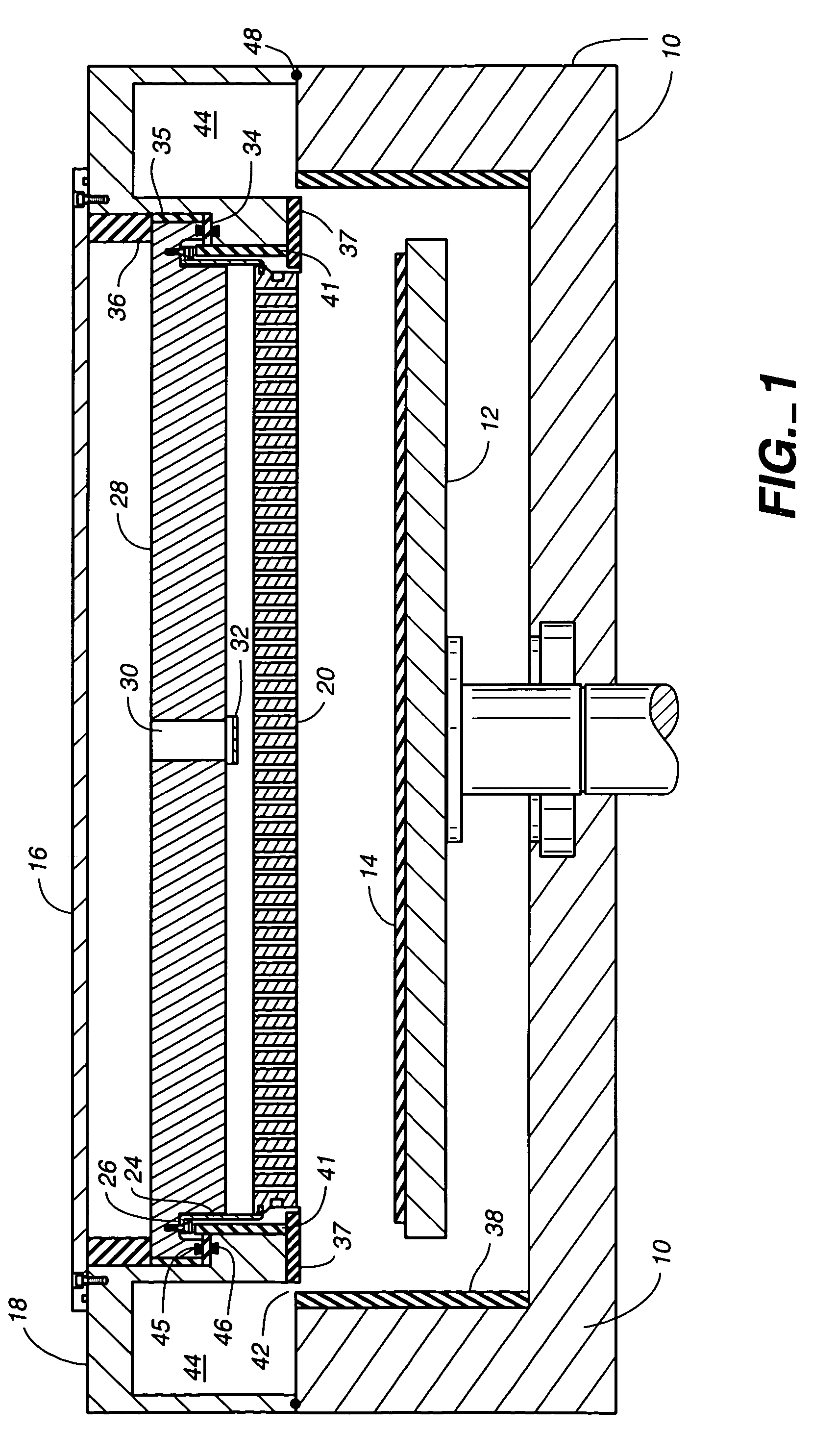
[0030]FIG. 1 shows a plasma chamber that includes a gas inlet manifold 20-32, also called a gas distribution manifold or plenum, according to the present invention. The illustrated chamber is suitable for performing plasma-assisted processes such as chemical vapor deposition (CVD) or etching on a large substrate. It is especially suitable for performing CVD processes for fabricating the electronic circuitry of a flat panel display on a glass substrate.

[0031]The plasma chamber or vacuum chamber has a housing or wall 10, preferably composed of aluminum, that encircles the interior of the chamber. The chamber wall 10 provides the vacuum enclosure for the side, and much of the bottom, of the chamber interior. A metal pedestal or susceptor 12 functions as a cathode electrode and has a flat upper surface that supports a workpiece or substrate 14. Alternatively, the substrate need not directly contact the susceptor, but may be held slightly above the upper surface of...


PUM

PropertyMeasurementUnit
widthaaaaaaaaaa
frequencyaaaaaaaaaa
thickaaaaaaaaaa

Abstract

A gas inlet manifold for a plasma chamber having a perforated gas distribution plate suspended by a side wall comprising one or more sheets. The sheets preferably provide flexibility to alleviate stress in the gas distribution plate due to thermal expansion and contraction. In another aspect, the side wall provides thermal isolation between the gas distribution plate and other components of the chamber.

Description

CROSS REFERENCE TO RELATED APPLICATIONS[0001]This patent application is a divisional of application Ser. No. 09 / 922,219 filed Aug. 3, 2001 now U.S. Pat. No. 6,772,827 by Ernst Keller et al., which is a continuation-in-part of application Ser. No. 09 / 488,612 filed Jan. 20, 2000 by John White et al., now U.S. Pat. No. 6,477,980.FIELD OF THE INVENTION[0002]The invention relates generally to gas distribution manifolds for supplying gas to a plasma chamber. More specifically, the invention relates to such a manifold having a perforated gas distribution plate suspended by a thin side wall.BACKGROUND OF THE INVENTION[0003]Electronic devices, such as flat panel displays and integrated circuits, commonly are fabricated by a series of process steps in which layers are deposited on a substrate and the deposited material is etched into desired patterns. The process steps commonly include plasma enhanced chemical vapor deposition (CVD) processes and plasma etch processes.[0004]Plasma processes r...

Claims


Application Information

Patent Timeline
Patent Type & Authority Patents(United States)
IPC IPC(8): C23C16/455C23C16/50C23C16/06C23C16/22B01J19/08C23C16/44C23C16/509H01J37/32H01L21/205H01L21/302H01L21/3065H01L21/31H05H1/46
CPCC23C16/455C23C16/45565H01J37/3244C23C16/5096Y10T29/49948H01J37/32
Inventor KELLER, ERNSTSHANG, QUANYUAN
Owner APPLIED MATERIALS INC
Why Eureka
Try Eureka