Vehicle and control method of vehicle

a technology of vehicle and control method, which is applied in the direction of electric propulsion mounting, battery/cell propulsion, gear locking, etc., can solve the problem that the ring gear cannot be locked with a sufficient level, and achieve the effect of suppressing the excessive increase of the temperature of the motor system, increasing the driving force range, and effectively preventing the rotation of the rotating sha

Active Publication Date: 2010-04-01
TOYOTA JIDOSHA KK
View PDF2 Cites 17 Cited by
  • Summary
  • Abstract
  • Description
  • Claims
  • Application Information

AI Technical Summary

Benefits of technology

[0009]In one preferable application of the vehicle of the invention, the driving force range is set to a narrower range when a temperature of the motor system is more than a preset temperature than a range that is set when the temperature of the motor system is less than or equal to the preset temperature. An electric current flowing through the motor is comparatively small when the temperature of the motor system is relatively high, in the case of applying an increasing electric current through the motor with an increase of the driving force range. Therefore, the vehicle of the application enables suppression of an excessive increase of the temperature of the motor system. Additionally, the vehicle performs the motoring of the engine while the motoring structure outputs the driving force that makes the shaft driving force within the driving force range. The vehicle of the application effectively prevents rotation of the rotating shaft even when the electric current flowing through the motor is relatively decreased. In this application, the vehicle further has: a temperature rise estimating module configured to estimate that the temperature of the motor system may rise over the preset temperature. The driving force range is set to a narrower range when the temperature rise estimating module estimates the temperature of the motor system may rise over the preset temperature than a range that is set when the temperature rise estimating module does not estimate that the temperature of the motor system may rise over the preset temperature. The vehicle of this application more effectively enables suppression of the excessive increase of the temperature of the motor system.
[0010]In another preferable application of the vehicle of the invention, the driving force range is set to a narrower range when a discharge power from the accumulator unit is over a preset electric power based on an output limit of the accumulator unit than a range that is set when the discharge power from the accumulator unit is less than or equal to the preset electric power. An electric current flowing through the motor is comparatively small when the discharge power from the accumulator unit is over the preset electric power, in the case of applying an increasing electric current through the motor with an increase of the driving force range. Therefore, the vehicle of the application enables suppression of an excessive increase of the discharge power from the accumulator unit. Additionally, the vehicle performs the motoring of the engine while the motoring structure outputs the driving force that makes the shaft driving force within the driving force range. The vehicle of the application effectively prevents rotation of the rotating shaft even when the electric current flowing through the motor is relatively decreased. In this application, the vehicle further has: an electric power excess estimating module configured to estimate that the discharge power from the accumulator unit may exceed the preset electric power. The driving force range is set to a narrower range when the electric power excess estimating module estimates that the discharge power from the accumulator unit may exceed the preset electric power than a range that is set when the electric power excess estimating module does not estimate that the discharge power from the accumulator unit may exceed the preset electric power. The vehicle of this application more effectively enables suppression of the excessive increase of the discharge power from the accumulator unit.
[0012]In another preferable embodiment of the vehicle of the invention, the control module controls the motoring structure to output the driving force that makes the driving force applied to the rotating shaft within a second driving force range that is narrower than the driving force range. The vehicle of this application more effectively enables restriction of rotation of the rotating shaft.

Problems solved by technology

The ring gear may be unable to be locked with a sufficient level due to insufficient flow of the electric current through the second motor depending on a state of the second motor or a state of the battery.

Method used


Image

  • Vehicle and control method of vehicle
  • Vehicle and control method of vehicle
  • Vehicle and control method of vehicle

Examples


Embodiment Construction

[0026]One mode of carrying out the invention is described below as a preferred embodiment.

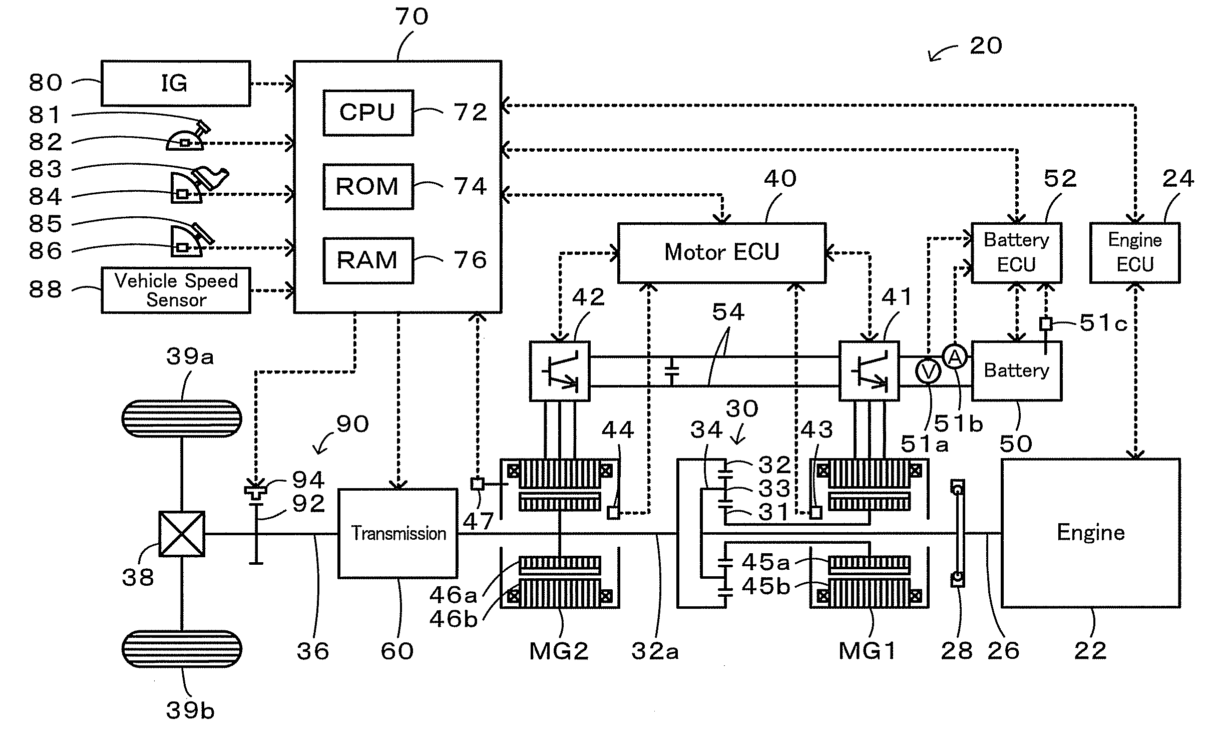
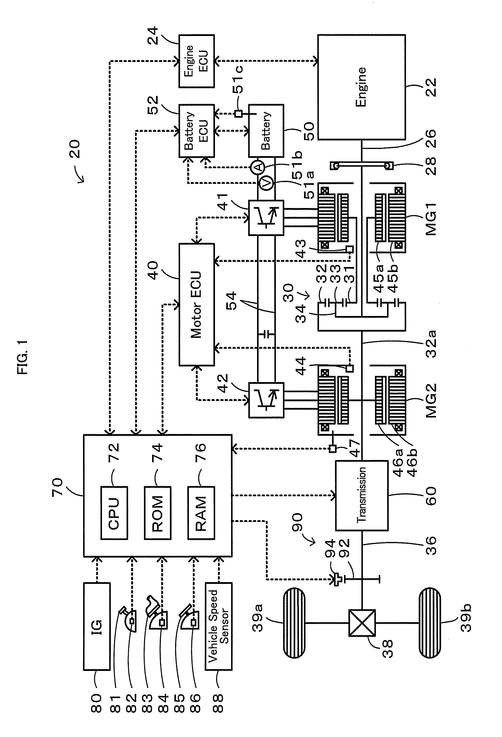
[0027]FIG. 1 schematically illustrates the configuration of a hybrid vehicle 20 in one embodiment of the invention. As illustrated, the hybrid vehicle 20 of the embodiment includes an engine 22, a three shaft-type power distribution integration mechanism 30 that is linked to a crankshaft 26 or an output shaft of the engine 22 via a damper 28, a motor MG1 that is linked to the power distribution integration mechanism 30 and has power generation capability, a motor MG2 that is linked to a ring gear shaft 32a or a rotating shaft connected to the power distribution integration mechanism 30, a transmission 60 that converts power of the ring gear shaft 32a and outputs the converted power to a driveshaft 36 connected to drive wheels 39a and 39b, a parking lock mechanism 90 that locks the drive wheels 39a and 39b, and a hybrid electronic control unit 70 that controls the operations of the whole hybrid ...


PUM


Abstract

In response to a starting instruction of an engine at a gearshift position of a gearshift lever set to a parking position, a motor is controlled to form a fixed magnetic field on a stator of the motor at the level that is capable of preventing rotation of a rotating shaft against a torque applied to the rotating shaft within magnitude less than or equal to magnitude of a rotation restriction control torque based on a temperature of the motor and a discharge power from the battery, a motor is controlled to perform the motoring of the engine while the motor outputs a torque that makes a torque applied to the rotating shaft less than or equal to magnitude of the rotation restriction control torque, and the engine is controlled to be started with the motoring.

Description

TECHNICAL FIELD[0001]The present invention relates to a vehicle and a control method of the vehicle.BACKGROUND ART[0002]A proposed configuration of a vehicle includes an engine, a planetary gear mechanism constructed to have a carrier linked with an crankshaft of the engine and a ring gear linked with drive wheels, a first motor linked with a sun gear of the planetary gear mechanism, a second motor linked with the ring gear, and a battery arranged to transfer electric power to and from the first motor and the second motor (see, for example, Patent Document 1). According to the vehicle, in response to a starting demand of the engine when the vehicle is parked, a lock position is first set based on a rotational position of the rotor of the second motor, for example, is selected as one of six. The ring gear is locked by the flow of electric current through two, phases corresponding to the set lock position among three phases to form the fixed magnetic field on a stator of the second mo...

Claims


Application Information

Patent Timeline
Patent Type & Authority Applications(United States)
IPC IPC(8): B60W10/04B60W20/00B60L50/16
CPCB60K1/02Y10T477/23B60K6/445B60K6/448B60K6/547B60L11/123B60L11/14B60L15/2009B60L15/2054B60L2240/423B60L2240/425B60L2240/441B60L2240/486B60L2260/52B60L2260/56B60W10/06B60W10/08B60W20/00B60W2510/0638B60W2510/087B60W2510/244B60W2540/10B60W2540/12B60W2540/16B60W2710/0616B60W2710/083F16H2037/0866Y02T10/6217Y02T10/6239Y02T10/6243Y02T10/6286Y02T10/642Y02T10/7005Y02T10/7077B60W30/192B60K2006/381B60W2510/186Y02T10/7275Y10T477/68Y10T477/653Y10T477/26B60K6/365Y02T10/72B60L50/61B60L50/16Y02T10/62Y02T10/64Y02T10/7072Y02T10/70B60K2006/268
Inventor SUGAI, SHINICHI
Owner TOYOTA JIDOSHA KK
Why Eureka
Try Eureka