Normally closed solenoid valve

a solenoid valve, closed technology, applied in the direction of valve details, valve arrangement, braking system, etc., can solve the problem of comparatively large difference in initial performan

Active Publication Date: 2007-07-10
AUTOLIV NISSIN BRAKE SYST JAPAN CO LTD
View PDF16 Cites 37 Cited by
  • Summary
  • Abstract
  • Description
  • Claims
  • Application Information

AI Technical Summary

Benefits of technology

[0009]According to this aspect of the invention, even if there are more or less differences in the initial positions of respective products, the initial thrust force of the movable core can be made constant only by setting the compression resiliency coefficient of a resilient biasing member when the attracting force of the movable core is increased by widening the areas of respective opposed planes of the fixed core and movable core. Therefore, even in a case where the current value to be supplied to the coil by current controlling means is made variable, it is possible to obtain a planned initial thrust force of the movable core, wherein respective products are freed from any unevenness. Further, since the compression resiliency coefficient, to be established, of a resilient biasing member can be obtained by securing the characteristic line of spacing distance between a fixed core and a movable core and the attracting force thereof in advance, the compression resiliency coefficient can be securely established.
[0011]With the structure as described above, it is possible to obtain a rough inclination even if the characteristic line of the spacing distance and attracting force in the assembling allowance range is not straight, and it is possible to make constant the thrust force of the movable core, which works against the biasing force of a resilient biasing member, in the assembling allowance range. Therefore, in the normally closed solenoid valve assembled in the assembling allowance range, it is possible to make roughly constant the initial thrust force of at least the movable core, wherein respective products will be almost freed from any unevenness. In addition, even in a case where the current value supplied to the coil is made variable by current controlling means, it is possible to secure a planned initial thrust force of the movable core, wherein the respective products will be free from any unevenness.
[0013]With the structure as described above, the valve body for which precise machining is required and a movable core which is long-sized and is comparatively easily machined may be produced in separate processes, whereby an efficiency can be achieved in the machining processes.
[0015]By this, even when the thrust force of a movable core is increased by widening the area of a surface opposed to the movable core, it is possible to make constant the initial thrust force in the initial position of the movable core by selecting or producing a spring member having a spring constant fitted to the characteristic line of spacing distance and thrust force.

Problems solved by technology

However, the characteristic lines S1 and S2 of spacing distance / attracting force produce steep slopes, and even in the assembling allowance range, there is a comparatively large difference in the initial performance.

Method used


Image

  • Normally closed solenoid valve
  • Normally closed solenoid valve
  • Normally closed solenoid valve

Examples


Embodiment Construction

[0021]Hereinafter, a detailed description is given of embodiments of the invention with reference to the drawings.

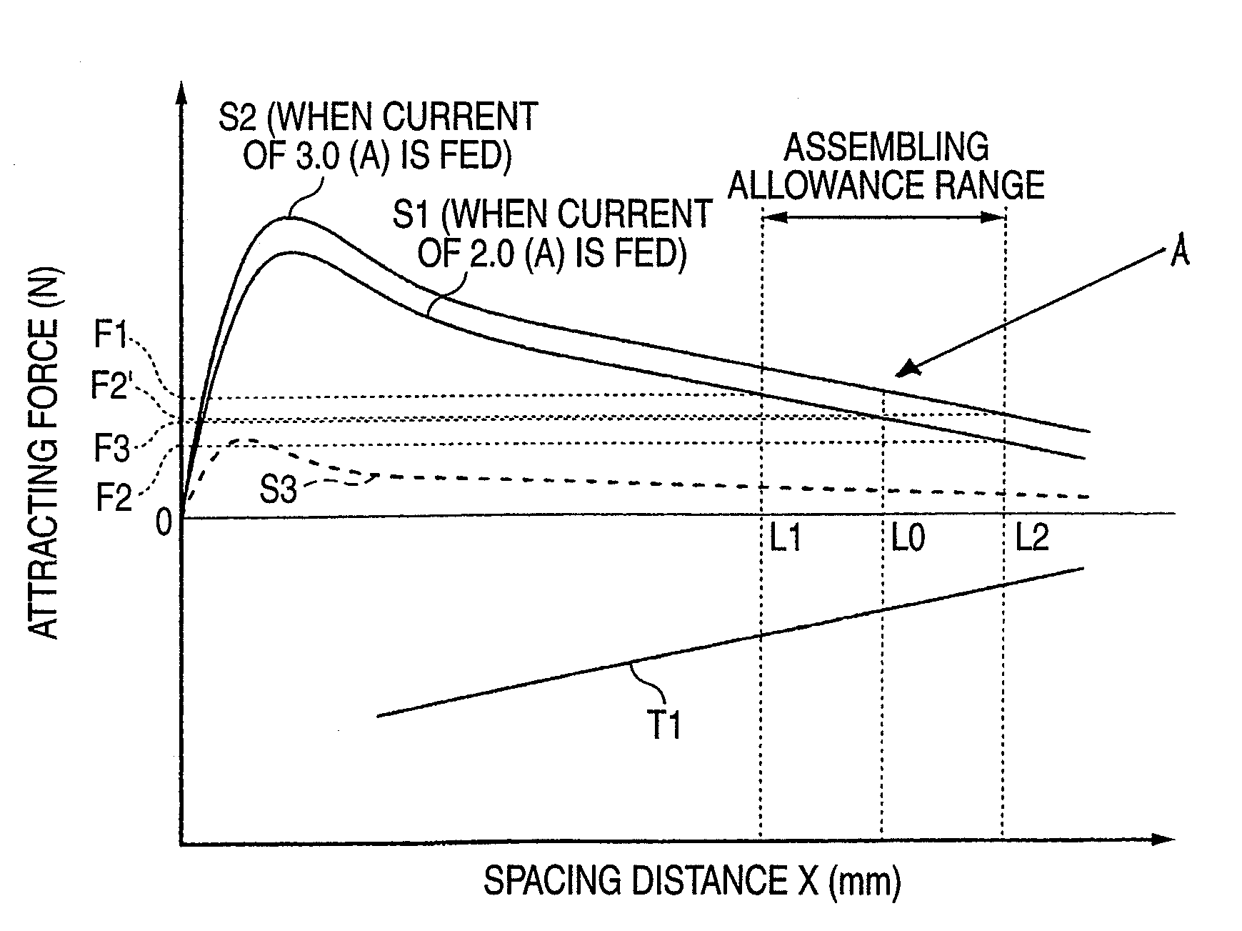
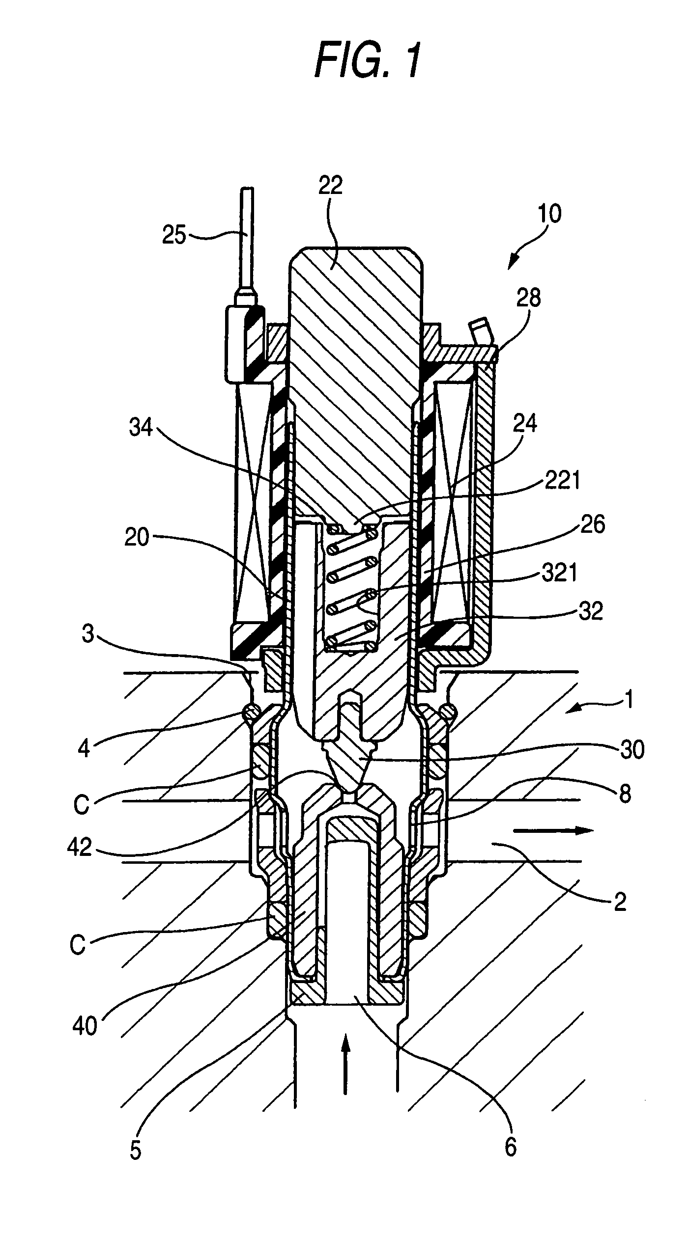
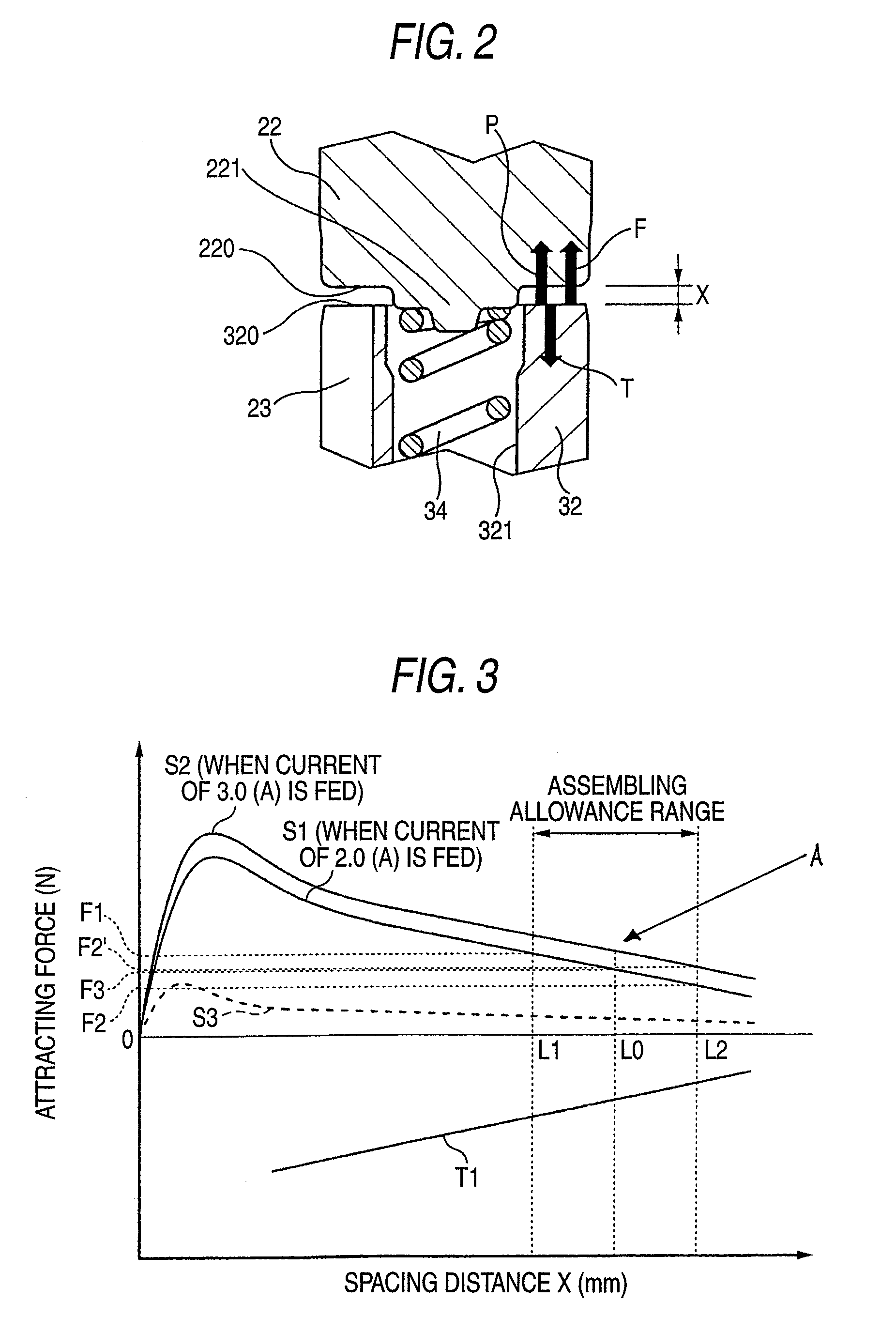
[0022]FIG. 1 is a longitudinal sectional view of a normally closed solenoid valve according to one embodiment of the invention, FIG. 2 is a partially enlarged longitudinal section view of a movable core and a fixed core, FIG. 3 is a graph showing the characteristic lines of spacing distance and thrust force of the normally closed solenoid valve and characteristic lines of spacing distance and spring force thereof, and FIG. 4 is a graph showing the characteristic line of spacing distance and thrust force of a normally closed solenoid valve according to one embodiment of the invention.

(Structure of a Normally Closed Solenoid Valve)

[0023]As shown in FIG. 1, a solenoid valve according to one embodiment of the invention is a normally closed solenoid valve 10 for opening and closing a flow path of a hydraulic fluid of, for example, an anti-lock brake system (ABS) for a vehicle...


PUM


Abstract

A normally closed solenoid valve includes a fixed core, a valve portion including a valve seat and a valve body, a movable core disposed between the fixed core and the valve seat, a resilient biasing member for biasing the movable core in a valve-closing direction and a coil. When energized, the coil generates an attracting force between the movable core and the fixed core against a biasing force by the resilient biasing member to cause the movable core to retreat from an initial position where the valve seat is in a closed state. When a characteristic graph line of spacing distance / attracting force that defines the attracting force in relation with a spacing distance between the fixed core and the movable core provides an inclination A (N / mm) at the initial position, the compression resiliency coefficient of the resilient biasing member is set to A (N / mm).

Description

BACKGROUND OF THE INVENTION[0001]1. Field of the Invention[0002]The present invention relates to a normally closed solenoid valve provided with a valve body for opening and closing a flow path of a hydraulic fluid.[0003]2. Background Art[0004]Conventionally, there are two types of solenoid valves for opening and closing a flow path of a hydraulic fluid, one of which is a normally closed solenoid valve that is normally closed and is opened by excitation of a fixed core and a movable core when a current is rendered to flow into a coil, and the other of which is a normally open valve that is normally opened and is closed by excitation of a fixed core and a movable core when a current is rendered to flow into a coil. Such a normally closed solenoid valve is provided with a valve seat for opening and forming a flow path of a hydraulic fluid and a valve body formed at the tip end of a movable core capable of being brought into contact with the valve seat and moving away therefrom. In a de...

Claims


Application Information

Patent Timeline
Patent Type & Authority Patents(United States)
IPC IPC(8): F16K31/02F16K31/06
CPCB60T8/363F16K31/0655F16K31/0693
Inventor KOMABA, TAKAAKIOHI, TAKESHI
Owner AUTOLIV NISSIN BRAKE SYST JAPAN CO LTD
Why Eureka
Try Eureka