Guidewire with internal pressure sensor

a technology of pressure sensor and guidewire, which is applied in the field of guidewires, can solve the problems of compromising the use of optimal solid core, difficult to weld nitinol to stainless steel, and high cost, and achieves the effect of optimizing mechanical performance and improving pushability

Active Publication Date: 2014-04-17
OPSENS
View PDF11 Cites 38 Cited by
  • Summary
  • Abstract
  • Description
  • Claims
  • Application Information

AI Technical Summary

Benefits of technology

This patent describes a device that improves the performance of pressure guidewires by optimizing their mechanical performance. Specifically, it improves their pushability, torquability, trackability, and catheter support. The device achieves this by routing sensor leads through the center of the guidewire instead of relying on a thin solid core for torque transfer. Additionally, the patent provides a mechanism to protect the vulnerable section of the guidewire against the risk of kinking.

Problems solved by technology

One consideration in designing guidewires is that welding nitinol to stainless steel is extremely challenging.
Nitinol is not preferred in this section because it does not provide a good pushability and torquability and it is fairly expensive.
Wall thickness of polyimide or wire winding added to the size of the sensor lead wires that runs along the solid core compromise the use of optimal solid core.
More specifically, the solid core is usually too thin for delivering adequate pushability and torquability on one hand, and adequate support for a balloon catheter on another hand.
The size of the distal portion of such a hypotube, the portion that navigates within the coronaries, that delivers optimal flexibility and torquability may however be susceptible to kinking, as it would have to be a fairly thin hypotube if made of stainless steel.
The joining of nitinol is however a challenging process and there is a risk of leaving any of the guidewire distal parts within the blood vessel.

Method used


Image

  • Guidewire with internal pressure sensor
  • Guidewire with internal pressure sensor
  • Guidewire with internal pressure sensor

Examples


Embodiment Construction

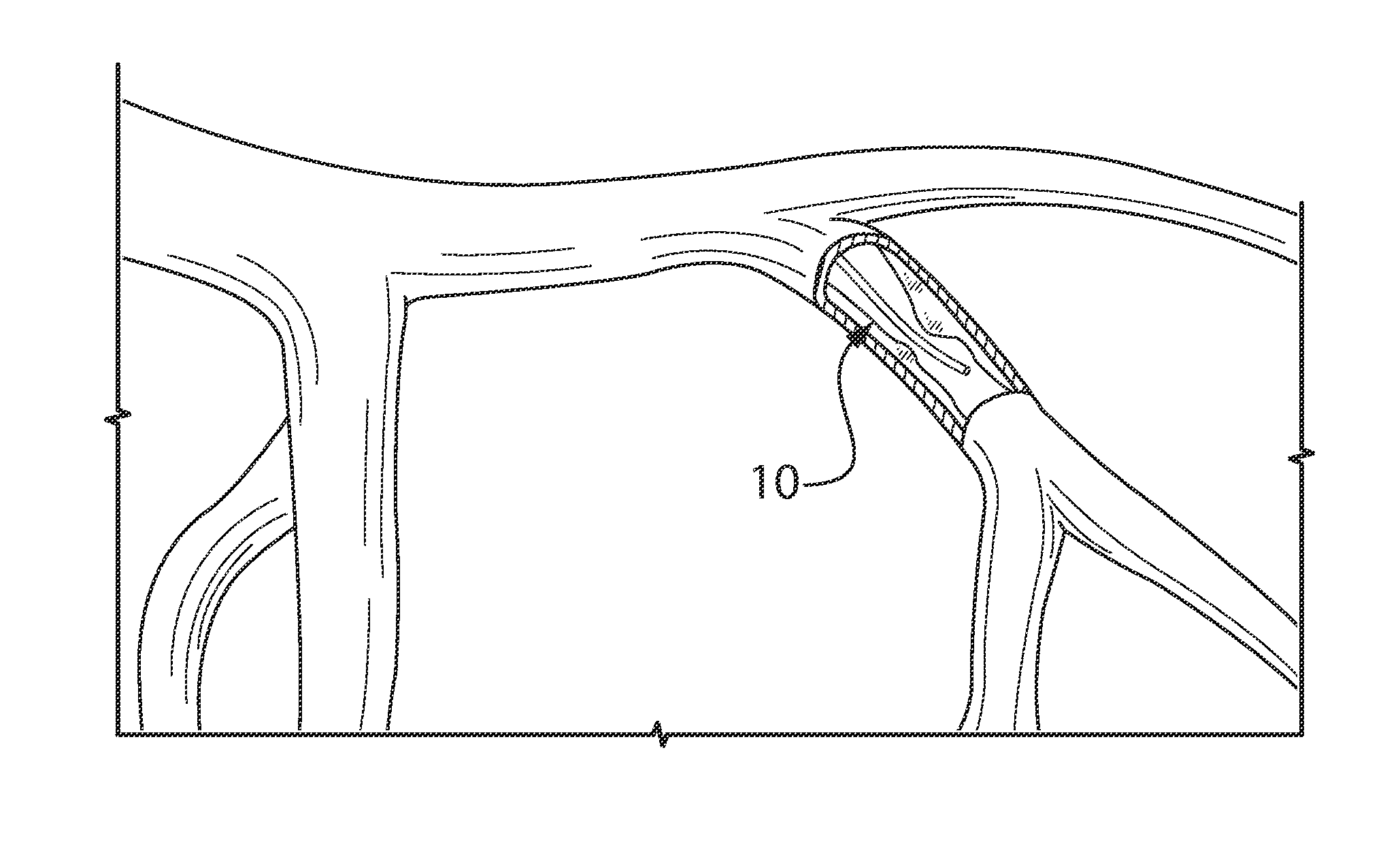
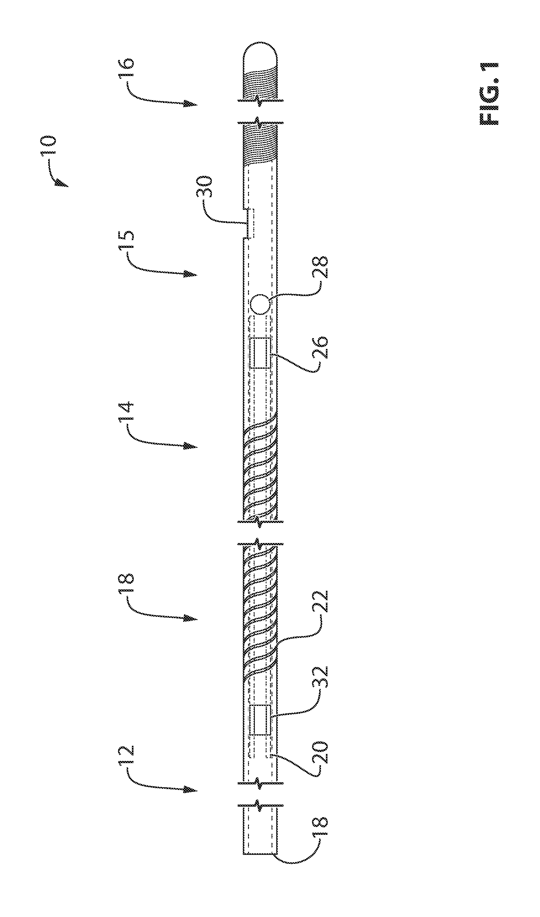
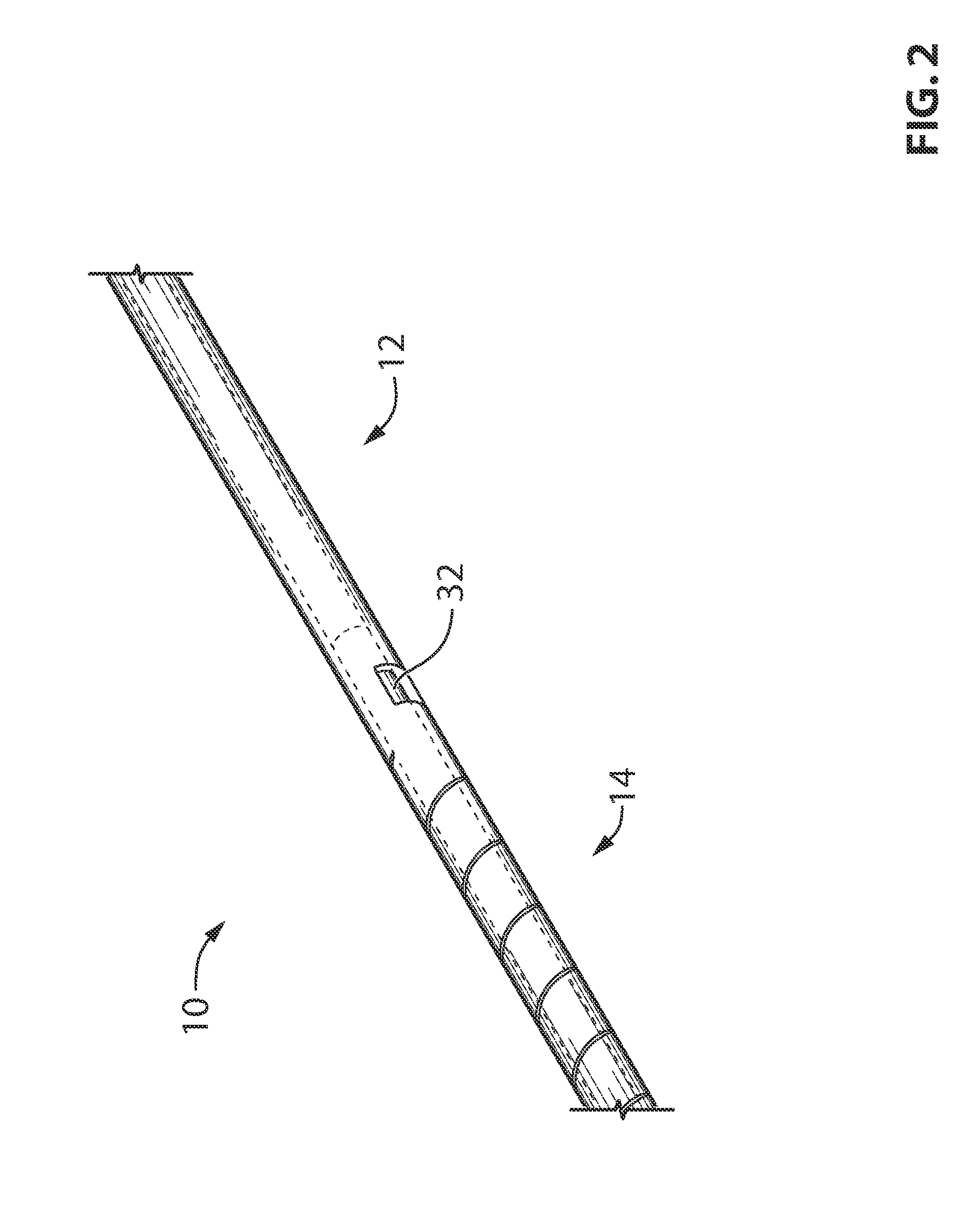
[0078]Referring now to the drawings, and more particularly to FIGS. 1 to 6, there is shown an embodiment of a pressure guidewire 10.

[0079]The general design for the pressure guidewire shown in FIG. 1 herein, although it is made of fewer parts than prior art pressure guidewires, it is also made of same four sections, namely, the proximal section 12, the middle section 14, the sensor housing section 15 and the tip section 16. Although, as it will become clear hereinafter, the first three sections 12, 14 and 15 are to some extent made of the continuity of the same shaft tube 18, the above sections of shaft tube 18 may also be called herein after as proximal section 12, middle section 14 and sensor housing section 15.

[0080]According to an embodiment, the proximal section 12 is made of a stainless steel hypotube, with an OD of about 0.014″ and by way of non limiting example with an ID of about 0.009″. The proximal section is used to push other more distal sections of the pressure guidewi...


PUM

PropertyMeasurementUnit
lengthaaaaaaaaaa
lengthaaaaaaaaaa
diameteraaaaaaaaaa

Abstract

The present document describes a pressure guidewire comprising: a shaft tube with a proximal section; a middle section extending from the proximal section of the shaft tube, the middle section having greater flexibility than the proximal section; an inner hypotube installed substantially within the middle section for optimal mechanical properties; a pressure sensor with a communication means routed through the middle section and the proximal section; and a sensor housing for receiving the pressure sensor. There are also described methods for joining the inner hypotube to the shaft tube.

Description

CROSS-REFERENCE TO RELATED APPLICATION[0001]This application is filed under 37 CFR 1.53(b) as a continuation application of U.S. patent application Ser. No. 14 / 030,425 filed Sep. 18, 2013. This application claims priority of U.S. patent application Ser. No. 14 / 030,425 filed Sep. 18, 2013 and U.S. patent application Ser. No. 13 / 389,319 filed Feb. 7, 2012 and PCT / CA2011 / 001257, filed Nov. 9, 2011, and entitled “GUIDEWIRE WITH INTERNAL PRESSURE SENSOR”, which claims priority of U.S. Provisional Application Ser. No. 61 / 411,722, filed on Nov. 9, 2010, the specifications of which are hereby incorporated herein by reference in its entirety.BACKGROUND[0002](a) Field[0003]The subject matter disclosed generally relates to guidewires for catheter use. More particularly, it relates to pressure guidewire technology.[0004](b) Related Prior Art[0005]Conventional Guidewires[0006]Conventional guidewires are made using solid rods. They may be made using a combination of different materials such as ha...

Claims


Application Information

Patent Timeline
Patent Type & Authority Applications(United States)
IPC IPC(8): A61M25/09
CPCA61M25/09A61M2025/0002A61M2025/09083A61M2025/09108A61M2205/3327A61M2025/09133A61M2025/09183A61B5/02154A61B5/0084A61B5/6851A61M2025/09166
Inventor BELLEVILLE, CLAUDE
Owner OPSENS
Why Eureka
Try Eureka