Production of agglomerates from gas phase

a technology of agglomerates and gas phase, which is applied in the field of production of agglomerates from gas phase, can solve the problems of low carbon nanotube production volume and high cost, and is prohibitive for its use as a filler material in most large-scale structural and electrical applications, and the current cvd process. , to achieve the effect of reducing the cost of carbon nanotube production, and reducing the cost of carbon nano

Active Publication Date: 2005-01-13
CAMBRIDGE ENTERPRISE LTD
View PDF9 Cites 156 Cited by
  • Summary
  • Abstract
  • Description
  • Claims
  • Application Information

AI Technical Summary

Benefits of technology

[0039] Preferably, air is prevented from entering the reactor as the agglomerate is removed from the reactor. This is particularly important where the diluent gas includes hydrogen, since otherwise an explosive mixture of hydrogen and air may be formed in the reactor.
[0040] Air may be prevented from entering the reactor in various ways. Suitably, the agglomerate is removed from the reactor via a U-tube trap containing liquid, for example silicone oil or a treatment liquid. The liquid acts as a seal to prevent air from entering the reactor. Gas from the reactor may escape via an exhaust pipe from the U tube.
[0041] Alternatively, the agglomerate may be removed from the reactor via a valve which prevents air from entering the reactor.

Problems solved by technology

The high cost and low production volume of carbon nanotubes are at present prohibitive for their use as a filler material in most large-scale structural and electrical applications.
Current CVD processes have the disadvantage that growing fibres condense at the low temperature region downstream of the reaction zone to form highly cross-linked networks.
The blocking of the gas flow leads to a significant change in pressure and chemical composition at the reaction zone, with the result that the structure of the products is changed and the overall yield is reduced.
This means that to achieve good results the products must be removed regularly, so that a continuous process is not possible.
In addition, the quality of the carbon nanotube products produced in this way is not controlled.
However, this document does not disclose how to control the process to produce such fibres in high yield.

Method used


Image

  • Production of agglomerates from gas phase
  • Production of agglomerates from gas phase
  • Production of agglomerates from gas phase

Examples


example 1

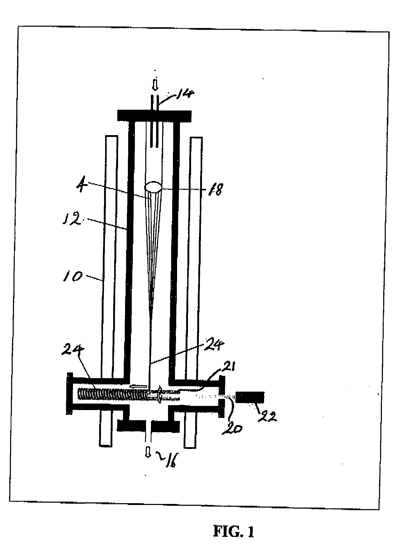
[0092] In a preferred embodiment of the invention, the process is carried out in the apparatus shown in FIG. 1. The apparatus comprises a vertically arranged cylindrical furnace 10 enclosing a vertically arranged cylindrical quartz reactor 12. Alternative reactors may be conical in shape. The reactor 12 has an inlet 14 at its upper end and an outlet 16 at its lower end. Positioned within the reactor 12 close to the inlet 14 is a nanotube catcher 18 in the form of a ring of metal wire. In alternative embodiments, the nanotube catcher 18 may be a ring of glass wire or of a magnetic material. Positioned within the reactor 12 close to the outlet 16 is a horizontally extending screw 20, suitably a stainless steel screw of 300 mm in length. In alternative embodiments, the screw may extend vertically or in other directions. The screw 20 is connected to a motor 22 and carries an internally threaded rod 21.

[0093] In use, the furnace 10 is heated to a high temperature. A solution of catalyst...

example 2

[0105] A process as set out above was carried out using a modified version of the apparatus of FIG. 1.

[0106] Spinning was conducted at the cold end of the reactor using a modified reactor with a cross piece at the end section of the tube. Spinning was normal to the gas stream. The spindle was made of a metal wire in a cubic shape (20×20×50 mm) in order to provide a large area for winding.

[0107] The spindle was located just out of the furnace at a temperature of about 100° C.

[0108] A solution of 2.3 wt % ferrocene and 3.0 wt % thiophene in ethanol was used as both the feedstock and catalyst precursor. This solution was injected through a needle into the top of the reactor (internal diameter 65 mm, 1400 nm long) which was heated to 1180° C. A catcher in the form of a thin metal rod was suspended from the lower part of the injector lance to encourage the formation of a long thin fibre. Without the catcher, the aerogel developed into a web traversing the tube below the hot zone, whic...

example 3

[0113] Multi-walled carbon nanotubes were produced using the reaction conditions of Example 1 and a modified version of the apparatus of FIG. 1.

[0114] The nanotubes were spun by using a mechanically driven spindle which was placed either at the furnace temperature with the spinning direction parallel to the gas stream or outside the furnace with the spinning direction normal to the gas stream. In the high temperature-spinning configuration, stainless steel studding (inner diameter 6 mm, 200 mm long) was used as the spindle. The studding was driven by a motor at the base of the reactor and rotated at 85 rpm at an angle of 5° from the vertical, The studding protruded 15 mm into the not zone (1180° C.) and the nanotubes were mainly wound onto this part of the spindle. The spinning process inside the reactor was observed via a mirror fixed at the base of the reactor and recorded by a video camera from outside of the reactor.

[0115] Scanning electronic microscopy showed good alignment o...


PUM

PropertyMeasurementUnit
temperatureaaaaaaaaaa
lengthaaaaaaaaaa
lengthaaaaaaaaaa

Abstract

A process for production of an agglomerate comprises the steps of: passing a flow of one or more gaseous reactants into a reactor; reacting the one or more gaseous reactants within a reaction zone of the reactor to form product particles; agglomerating the product particles into an agglomerate; and applying a force to the agglomerate to displace it continuously away from the reaction zone.

Description

FIELD OF THE INVENTION [0001] The present invention relates to a process for producing agglomerates, for example fibres or films of single-walled or multi-walled carbon nanotubes, and to agglomerates so produced. BACKGROUND OF THE INVENTION [0002] Carbon nanoparticles have received a great deal of attention since the discovery of the C60 buckminster fullerene molecule (H. W. Kroto, J. R. Heath, S. C. O'Brien, R. F. Curl and R. E. Smally, Nature 318, 162 (1985)) and the carbon nanotube (S. Ijima, Nature 354, 56 (1991)). Carbon nanoparticles are typically 1 to 100 nm in at least one dimension, carbon nanotubes however being up to a few millimetres in length. The explosion in C60 research in the early 1990s was driven by the production of large quantities (few milligrams) of the material by Krastchmer et al. (W. Kratschmer, L. D. Lamb, K. Fostiropoulos and D. R. Huffman, Nature 347, 354 (1990)) using a high pressure arc discharge method. [0003] The remarkable mechanical and electronic ...

Claims


Application Information

Patent Timeline
Patent Type & Authority Applications(United States)
IPC IPC(8): B29B9/00C01B31/02C04B35/622C04B35/80C12N11/04C23C16/26C23C16/44D01F1/00D01F9/127
CPCB82Y30/00B82Y40/00C01B31/0233C01B2202/02C01B2202/06C01B2202/34Y10S977/843C04B35/62272C04B35/6229C04B35/80C04B2235/5288D01F9/127C01B2202/36C01B32/162C23C16/44D01F1/00C23C16/26
Inventor KINLOCH, IAN ANTHONYLI, YALIWINDLE, ALAN H.CASH, STEPHEN LEE
Owner CAMBRIDGE ENTERPRISE LTD
Why Eureka
Try Eureka