Directional coupler and wireless communication device

a wireless communication and coupler technology, applied in the direction of coupling devices, electrical devices, transmission, etc., can solve the problems of significant influence of reflection on the deterioration of characteristics, insertion loss, isolation and directivity deterioration, etc., to prevent reflection

Active Publication Date: 2016-08-25
TDK CORPARATION
View PDF3 Cites 1 Cited by
  • Summary
  • Abstract
  • Description
  • Claims
  • Application Information

AI Technical Summary

Benefits of technology

[0025]In the coupler according to the present invention and respective aspects described above, the main line and sub-line are preferably configured to be ...

Problems solved by technology

As a result, the inventors newly found that undesired electromagnetic coupling arising between a sub-line and a terminal causes deteriorations in the isolation characteristic and directivity, and that the coupling between an output terminal and the sub-line particularly exerts significant influences on the deteriorations in characteristics.
The inventions described in the aforementioned Patent Document 1 (JP-A-2002-280810) and Patent Document 2 (JP-B2-3651401), though they provide for improvements in isolation, are disadvantageous in an insertion loss caused by a longer line l...

Method used


Image

  • Directional coupler and wireless communication device
  • Directional coupler and wireless communication device
  • Directional coupler and wireless communication device

Examples


Embodiment Construction

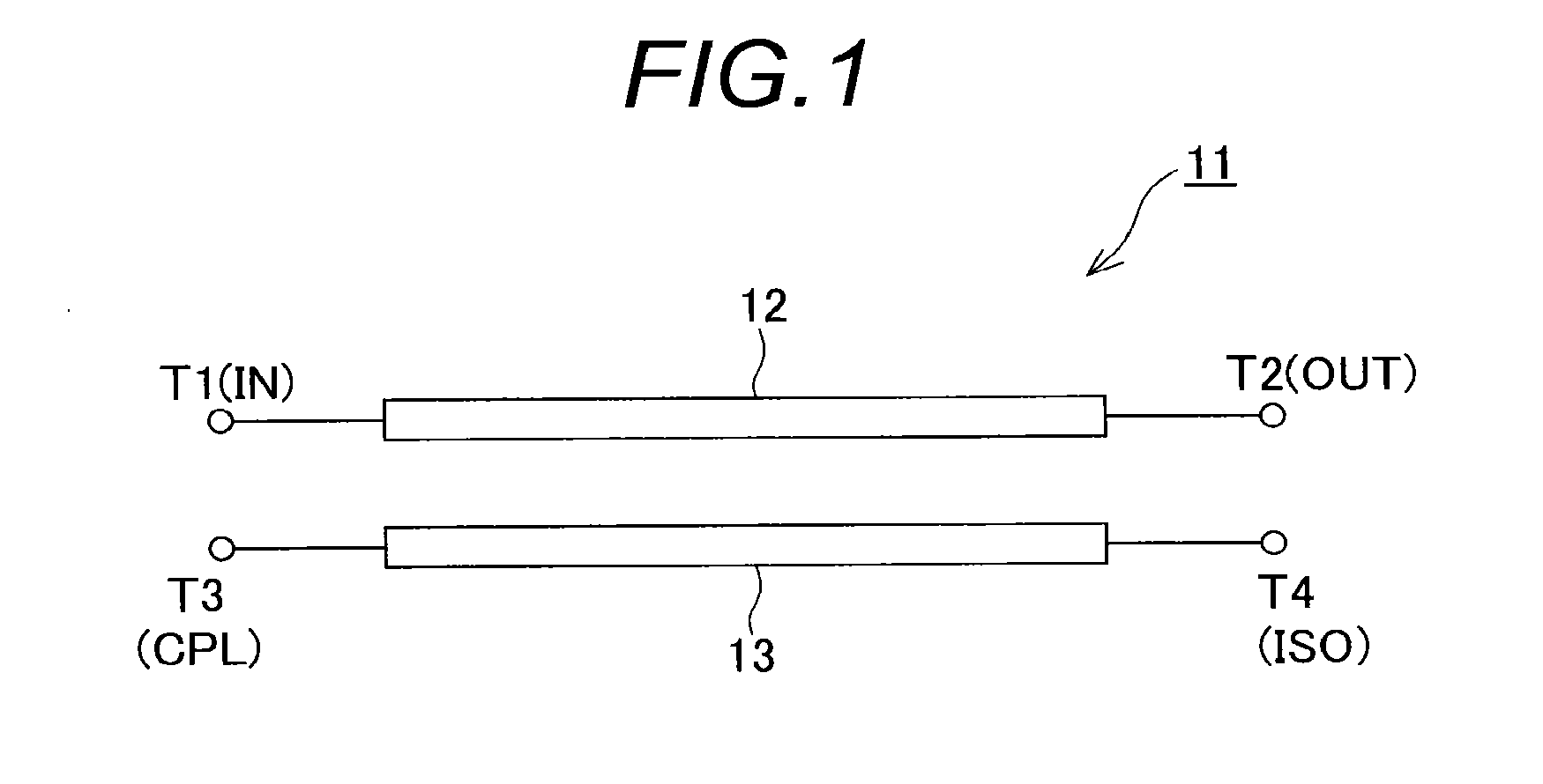
[0036]As illustrated in FIG. 1, a coupler 11 according to one embodiment of the present invention comprises a main line 12 for transmitting a transmission signal, and a sub-line 13 disposed in close proximity to the main line 12 such that electromagnetic coupling is generated therebetween. The main line 12 has an input terminal T1 at one end thereof, and an output terminal T2 at the other end thereof. The sub-line 13 in turn has a coupling terminal T3 at one end thereof, and an isolation terminal T4 at the other end thereof. Also, since these main line 12 and sub-line 13 as well as the respective terminals T1-T4 make up the coupler of this embodiment in the form of one-chip electronic component, they are arranged within a laminate which comprises a plurality of conductor layers laminated with insulating layers interposed between the respective conductor layers.

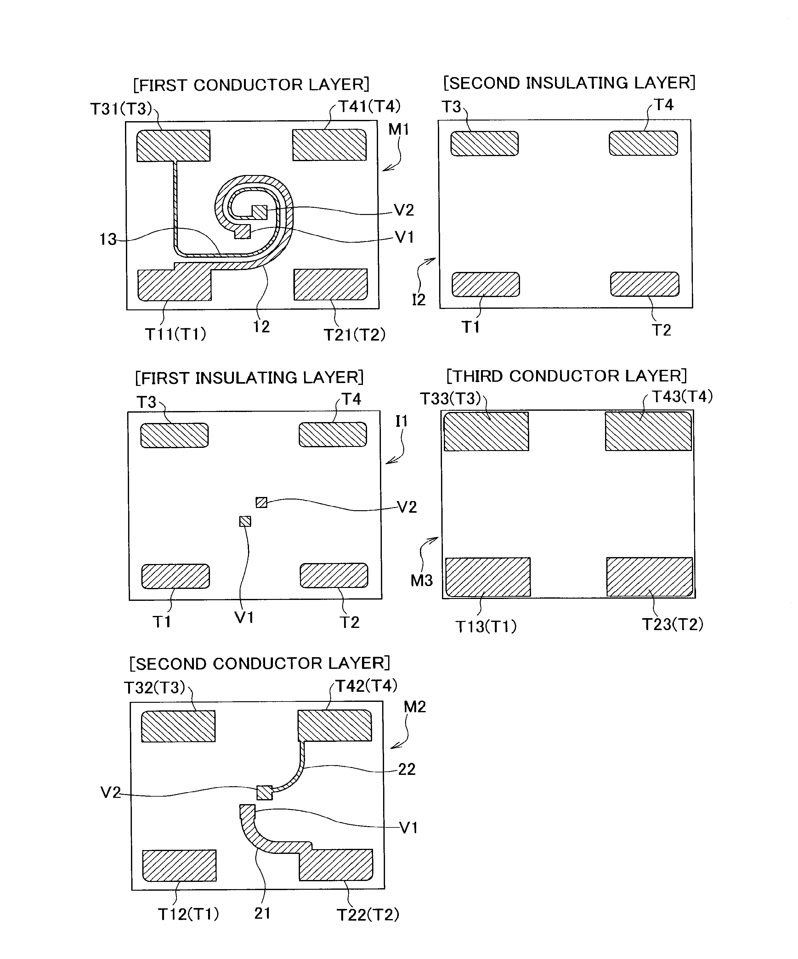
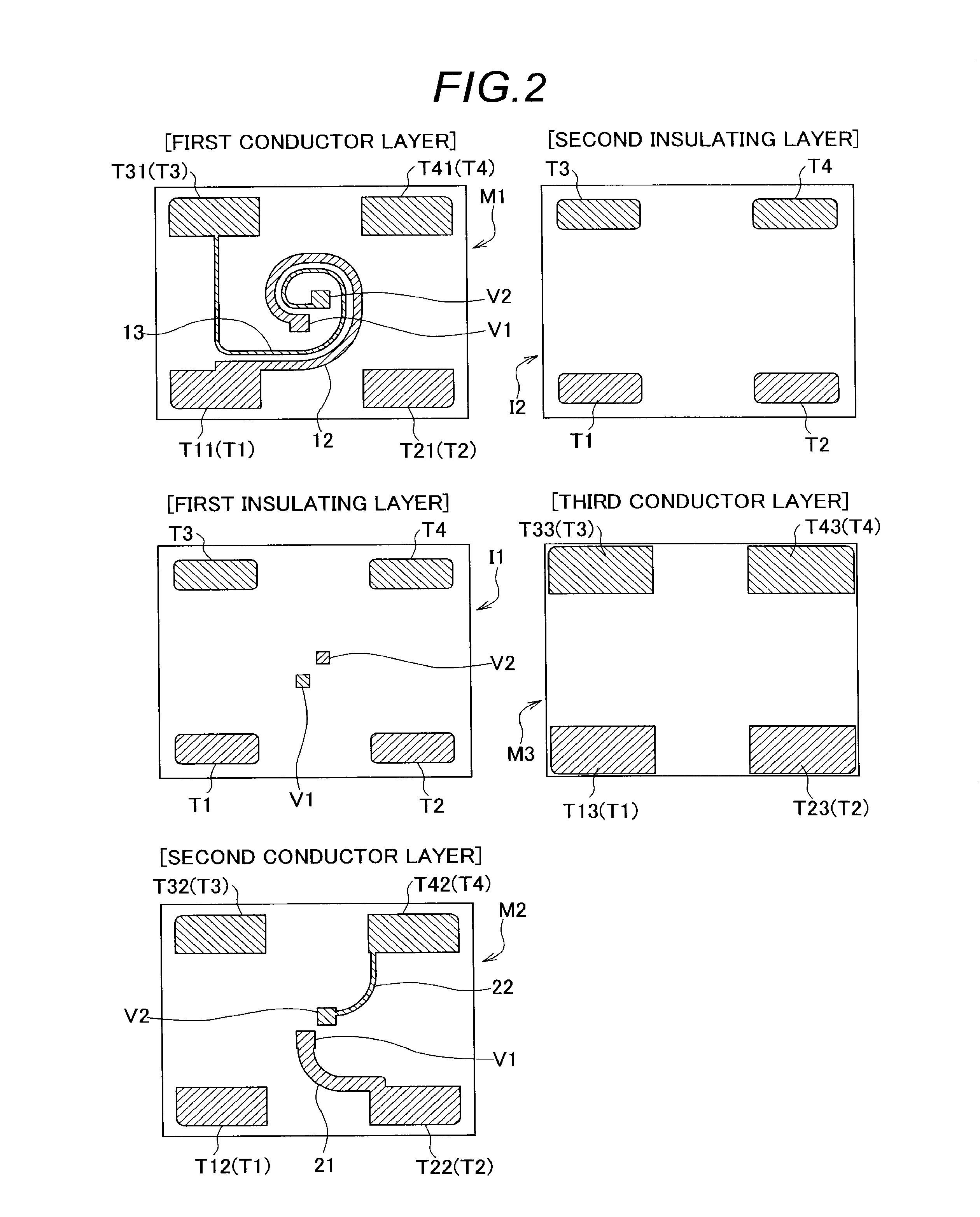
[0037]Specifically, the laminate has a rectangular geometry, as viewed in plane, as illustrated in FIG. 2, and includes a fi...


PUM


Abstract

A directional coupler including a main line having an input terminal and an output terminal, and a sub-line having a coupling terminal and an isolation terminal, the main line, the sub-line, the input terminal, the output terminal, the coupling terminal and the isolation terminal being disposed within a laminate, wherein the main line and the sub-line extend in a loop shape in parallel with and spaced apart from each other by a gap such that electromagnetic coupling is generated therebetween and such that the main line is positioned outside the sub-line on a coupling layer, the input terminal, the output terminal, the coupling terminal and the isolation terminal are disposed outside the main line, and the main line is interposed between the output terminal and the sub-line.

Description

BACKGROUND OF THE INVENTION[0001]The present invention relates to a directional coupler and a wireless communication device, and particularly, to technologies for improving the isolation characteristic and directivity of the directional coupler to reduce an insertion loss by bringing innovations into layouts of conductor patterns and the like within a laminate which forms part of the directional coupler.[0002]A directional coupler (hereinafter sometimes referred to as the “coupler”) for extracting part of electric power propagated through a transmission line is an indispensable part for constructing a transmission circuit for a variety of wireless communication devices such as a mobile phone, a wireless LAN communication device, a communication device conforming to the Bluetooth (registered trademark) standard, and the like.[0003]Specifically, a coupler forms part of adjusting means for controlling a transmission signal to keep its level constant, and this adjusting means comprises ...

Claims


Application Information

Patent Timeline
IPC IPC(8): H01P5/18H04B1/44
CPCH04B1/44H01P5/18H04B1/40H01P5/184
Inventor FUJIWARA, TOSHIYASULIN, CHENGBINOOHASHI, TAKESHIMITAKE, YUKIO
Owner TDK CORPARATION
Why Eureka
Try Eureka