Implant Conveying Device and Implanted Medical Instrument

a technology of conveying device and implant, which is applied in the field of medical instruments, can solve the problems of increasing unpredictable biological risk, and thrombosis source at the implant, so as to reduce the amount of metal remaining in the human body, avoid thrombosis sources, and reduce potential biological risks

Active Publication Date: 2016-11-03
LIFETECH SCIENTIFIC (SHENZHEN) CO LTD
View PDF23 Cites 10 Cited by
  • Summary
  • Abstract
  • Description
  • Claims
  • Application Information

AI Technical Summary

Benefits of technology

[0018]Compared with the prior art, the present invention has the following advantages. 1. The conveying device of the present invention does not need to be additionally provided with a locking ring on the surface of the implant, so that the amount of metal remaining in the human body is reduced after the implant is implanted into the human body, thereby reducing potential biological risk and avoiding a thrombus source for the implant. 2. The length of the connecting wire in the conveying device of the present invention may be freely adjusted during a process of assembling with the lock, so that the difficulty in controlling the length of the locking ring in the production process is reduced, and the production yield in the assembling process is improved.

Problems solved by technology

The lock ring is formed at the implant; after the implant is implanted into the human body, the lock ring is also implanted into the human body, resulting in the increase in the amount of metal remaining in the human body.
This increase of the amount of metal means the increase of the amount of metal elements released in the human body, resulting in unpredictable biological risk, 2.
After the implant is implanted into the human body, it is possible that the lock ring and the surface of the implant are not fitted closely; so that the endothelial tissue subsequently may not completely cover the lock ring, thereby resulting in a thrombus source at the implant.

Method used


Image

  • Implant Conveying Device and Implanted Medical Instrument
  • Implant Conveying Device and Implanted Medical Instrument
  • Implant Conveying Device and Implanted Medical Instrument

Examples


Embodiment Construction

[0029]In order to make the objectives, the technical solutions and the advantages of the present invention more clear, the present invention will be further described in detail with reference to the accompanying drawings and the embodiments. It should be understood that the specific embodiments described here is merely used for explaining the present invention, but not for limiting the present invention.

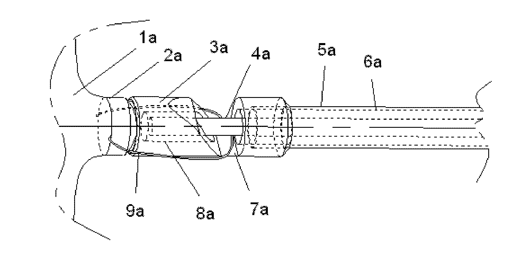
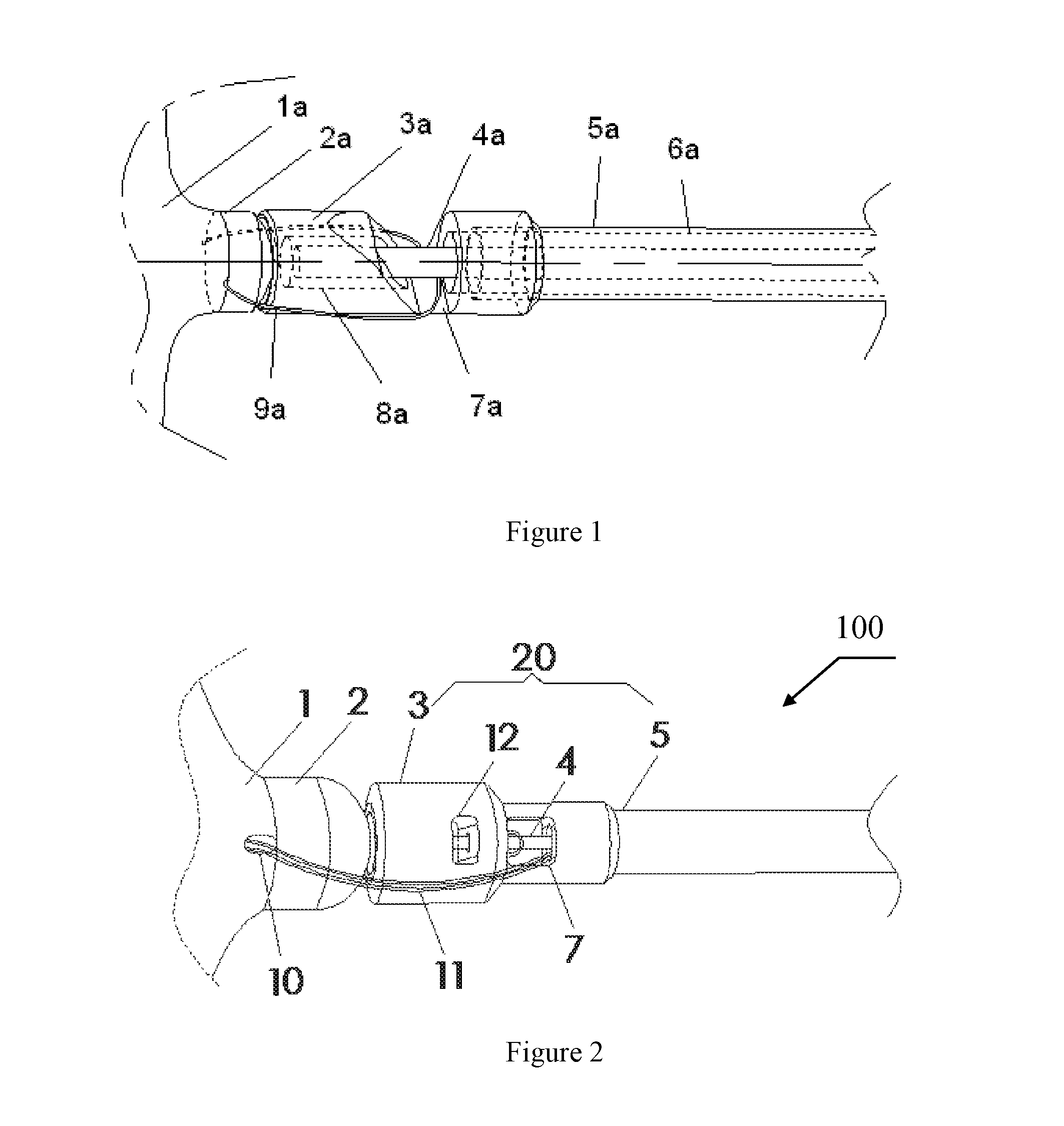
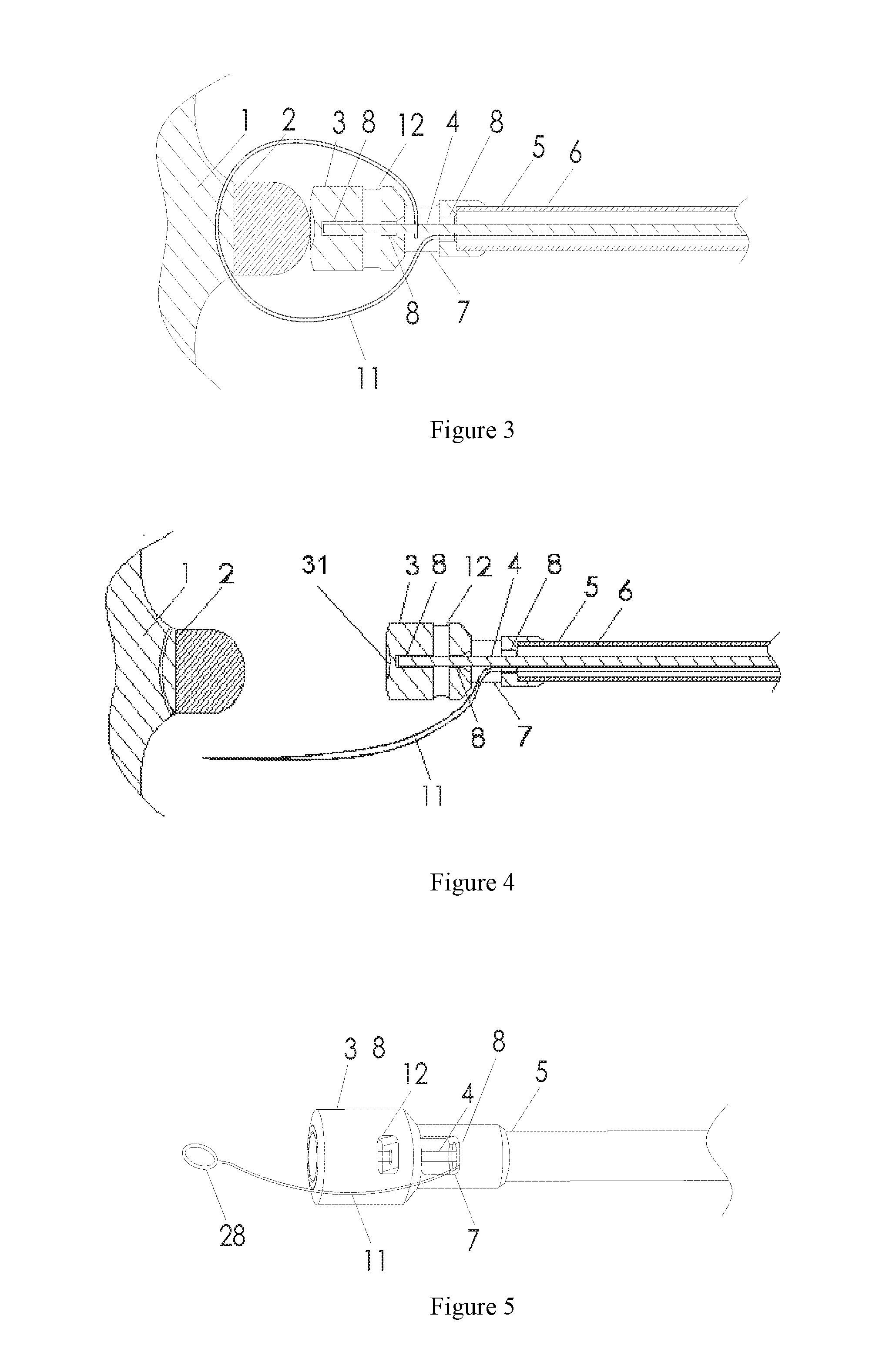
[0030]One embodiment of the present invention provides an implanted medical instrument 100, as shown in FIG. 2, FIG. 3 and FIG. 10, including an implant 1 and a conveying device configured to deliver the implant 1. The conveying device mainly includes a pusher 20 and a control component 21 (as shown in FIG. 10). A through hole is defined at the distal portion of the implant 1. In the embodiment, the implant 1 is a heart occluder. The pusher 20 includes a catheter 5 and a lock 3.

[0031]Further as shown in FIG. 4 to FIG. 10, a closure head 2 configured to bring ends of metal wires of th...


PUM


Abstract

The present invention relates to an implant conveying device, comprising a pusher (20), a control component (21), a connecting wire (11) and a control wire (4). The pusher (20), of which one end is connected to the control component (21), is provided with a tube cavity (6) and a lock hole (7) communicated with the tube cavity. One end of the control wire (4) is connected to the control component (21), and the other end thereof is driven by the control component to be movably accommodated in the tube cavity (6) of the pusher. One end of the connecting wire (11) is connected to the pusher (20) or to the control component (21), and the other end thereof is used for passing through an implant (1) and then entering the lock hole (7). The control wire (4) is driven by the control component (21) to pass through the connecting wire (11) to connect the implant (1) and the conveying device, or the control wire (4) is driven by the control component (21) to be disengaged from the connecting wire (11) to release the implant (1). By means of the conveying device, locking rings on instruments are removed, so that no redundant metal remains after the implant is implanted into the human body.

Description

TECHNICAL FIELD[0001]The present invention relates to medical instruments, in particular to an implant conveying device and an implanted medical instrument including the conveying device.BACKGROUND OF THE PRESENT INVENTION[0002]Percutaneous interventional technology is a therapeutic method with an increasingly wider application field. A variety of implants, such as a heart defect occluder, a vascular plug, a vascular filter and the like, may be placed into the heart and the artery and vein vessels of the human body by using catheter interventional therapy.[0003]When these implants are implanted into the heart and the artery and vein vessels of the human body through the catheter interventional method, due to the complex anatomical structures of the heart and the artery and vein vessels of the human body, a catheter, a guide wire and a pusher must be used to ensure that the implant reaches a predetermined position. The catheter first reaches the predetermined position under the guida...

Claims


Application Information

Patent Timeline
Patent Type & Authority Applications(United States)
IPC IPC(8): A61F2/01
CPCA61F2002/011A61F2/01A61B17/0057A61B17/12109A61B17/12145A61B2017/00623A61B2017/1205A61F2/011A61B17/12122A61B2017/12054A61F2220/0075
Inventor LIU, XIANGDONGCHEN, JIEZHANG, ZHIWEI
Owner LIFETECH SCIENTIFIC (SHENZHEN) CO LTD
Why Eureka
Try Eureka