Door or window hinge

Inactive Publication Date: 2017-06-01
SIMONSWERK
View PDF9 Cites 8 Cited by
  • Summary
  • Abstract
  • Description
  • Claims
  • Application Information

AI Technical Summary

Benefits of technology

[0014]The housing of the inventive hinge usefully has two side walls connected by top and bottom walls, forming a box open in the direction. The rack is on a first side wall and the second side wall preferably has an opening into which the

Problems solved by technology

Another disadvantage of the known hinge may be found in that, when the hinge is in the closed condition, the moveable members o

Method used


Image

  • Door or window hinge
  • Door or window hinge
  • Door or window hinge

Examples


Embodiment Construction

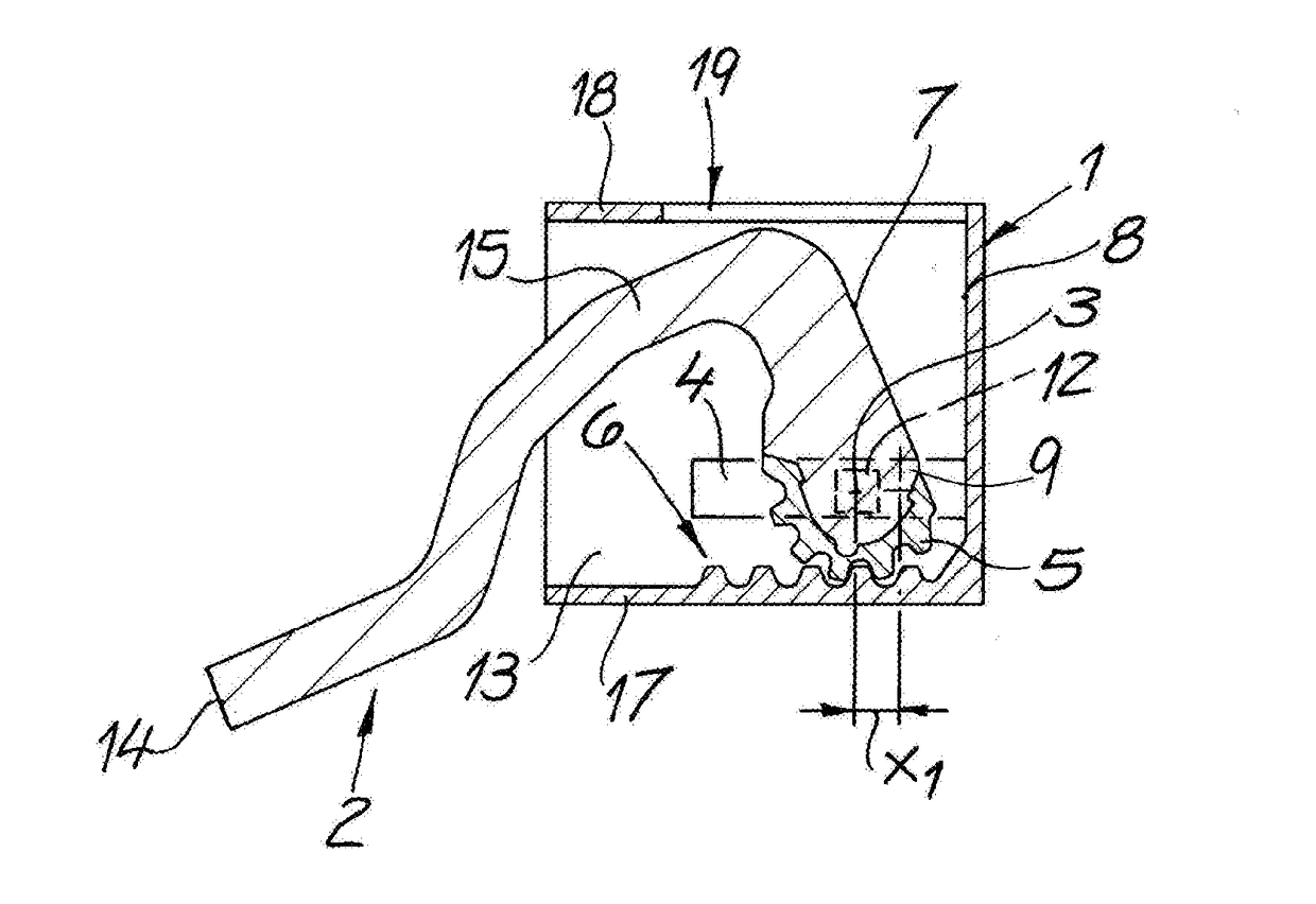
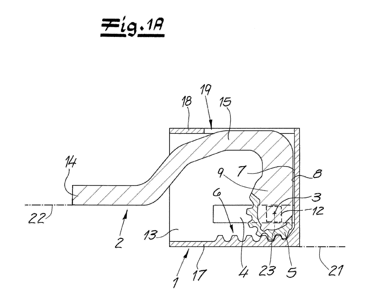
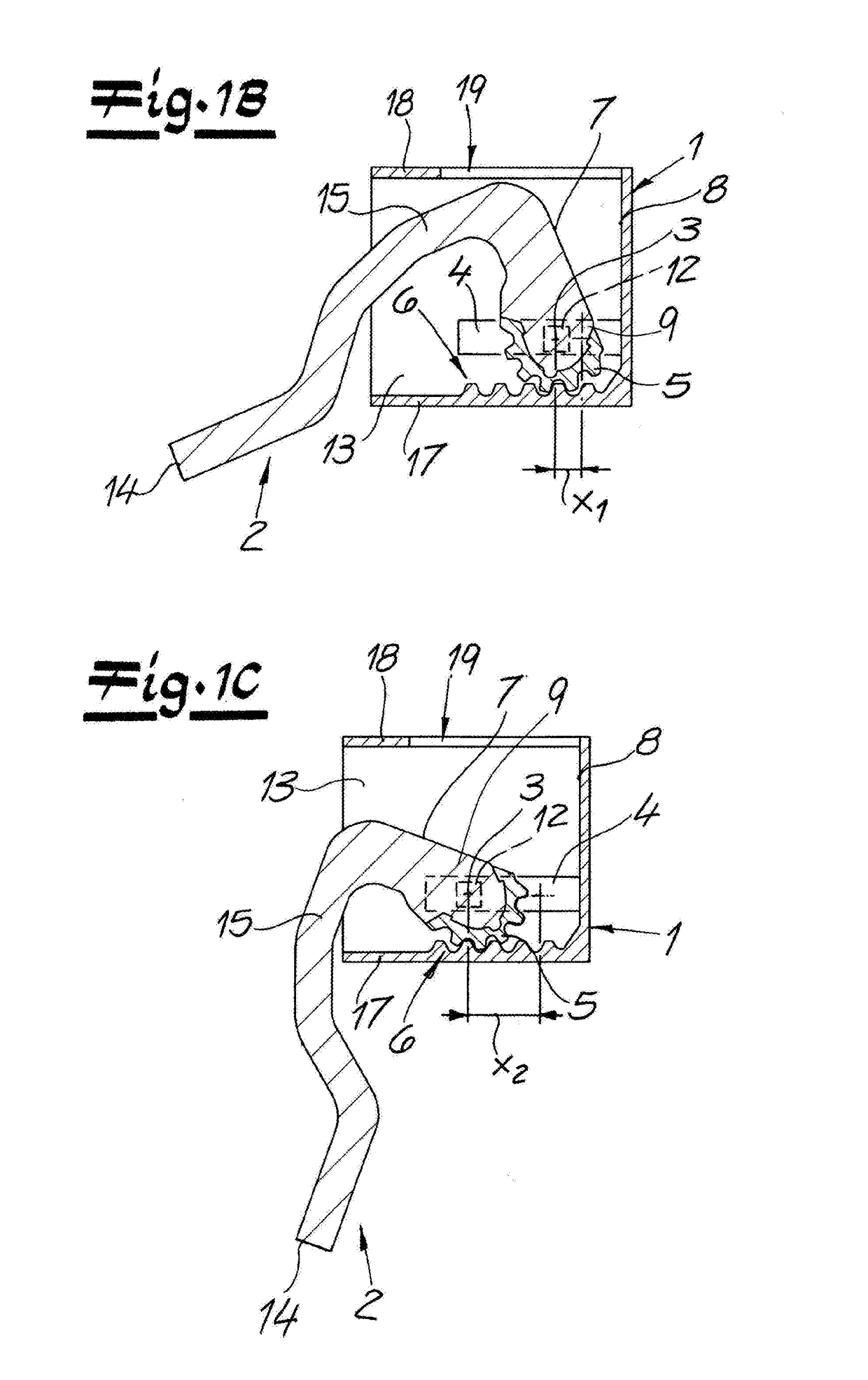
[0020]As seen in FIGS. 1A through 1D a hinge intended to be concealed when the door or window it is used with is closed comprises as a parallepipedal and box-like housing 1 and a largely metal hinge body 2 that is pivotal about a here vertical hinge axis 3 in the housing 1 typically seated in a door jamb shown schematically at 21. The hinge axis 3 is defined by an unillustrated cylindrical pivot shaft seated in a bore 20 (FIG. 4) of the hinge body 2 and having upper and lower ends 12 of square section and slidable in respective guide tracks or slots 4 formed in upper and lower plates 13 fixed in the housing 2. The hinge body 2 has an inner end 9 formed with an array of parallel radially outwardly directed teeth forming a sector gear 5 that, during a pivot movement of the hinge body 2, rotates about the hinge axis 3 to move the hinge between a closed position and a open position on a straight row of teeth forming a rack 6 on an inside face of a side wall 17 of the housing 1. The hing...


PUM


Abstract

A door or window hinge has a housing having a back wall facing in a predetermined direction and a side wall extending in the direction from the back wall. A rack fixed to the side wall and extending in the direction meshes with a sector gear fixed to an inner end of a hinge body and formed as a partial ellipse having a semimajor axis. The inner body end can rotate in the housing about an axis perpendicular to the direction and slides in the guide in the direction between a closed position with a stop face of the inner end bearing on the back wall and an open position with the inner end spaced in the direction from the back wall. The sector gear is oriented on the inner end such that in the closed position the semimajor axis extends substantially perpendicular to the direction.

Description

FIELD OF THE INVENTION[0001]The present invention relates to a hinge. More particularly this invention concerns a concealed hinge adapted for carrying a door or window.BACKGROUND OF THE INVENTION[0002]A hinge for doors or windows is known a housing and a hinge body rotatable about a hinge axis in the housing. This hinge axis is formed by structure that is displaceable in the housing along a guide track. The hinge body has an inner end provided with a sector gear that, during a pivot movement of the hinge body, rolls about its hinge axis between a closed position and an open position on a rack inside of the housing. The inner end of the hinge body has a stop face that in the closed position is positioned against a bottom face of a back wall of the housing.[0003]When the door or window is closed, the hinge is hidden between the frame and door or window panel and is not visible from outside. One preferred field of use for the hinge is doors for residential and office spaces as well as ...

Claims


Application Information

Patent Timeline
IPC IPC(8): E05D11/00E05D11/06F16H19/04E05D3/02
CPCE05D11/00E05D11/0054E05D2011/0072E05D11/06F16H19/04E05D3/02E05D3/022E05Y2201/71E05Y2600/41E05D5/06E05D2005/067E05Y2201/712E05Y2201/722E05Y2900/148E05Y2900/132
Inventor KNOECHEL, JENS
Owner SIMONSWERK
Why Eureka
Try Eureka