[0030] (a) to provide a decrease in weight and installation space by using one compact unit—a hybrid two cycle engine, compressor and pump instead of two conventional separate units engine and pump;
[0031] (b) to provide an increase in engine power through use of a
high pressure air injection reciprocation compressor, using the space below the engine piston as a compressor chamber, with volume greater than the
engine displacement volume;
[0032] (c) to provide direct energy transmission from the engine piston to the pump
plunger through its stationary connection, thereby increasing efficiency with decreasing fuel consumption;
[0033] (d) to provide direct energy transmission by using the interaction between the bottom of the engine piston and top of the compressor piston for
air compression, thereby increasing efficiency and decreasing the fuel consumption;
[0034] (e) to provide increased
longevity and efficiency by moving the engine, compressor pistons and pump plunger without cross forces during the
power transmission;
[0035] (f) to provide a simple and high quality balancing reciprocating movement by moving the engine and compressor pistons in opposite directions;
[0036] (g) to provide an increase in engine power by simultaneously moving the engine piston upward and using the high pressurized air from the
receiver which was compressed in the previous
stroke while the said engine piston moved downward;
[0037] (h) to provide intensive filling of the
combustion chamber while the engine piston moves to the top end position and simultaneously super
high pressure air is injected from the
receiver via the air injection valve within the
combustion chamber;
[0039] (j) to provide an increase in the pump power by locating the pump plunger on the rotor centerline;
[0040] (k) to provide an increase in the pump power by direct energy transmission from engine piston to pump plunger;
[0041] (l) to provide a high power
starter able to
fast start and restart an engine, and to
shut down at every red traffic light with decreased fuel consumption, by using a pneumohydraulic accumulator and the pump plunger in high power
hydraulic cylinder mode;
[0042] (m) to provide quick pedal starting independent of
external energy sources with use of a starter pump and pneumohydraulic accumulator;
[0043] (n) to provide starting power even if the vehicle is not driven for a lengthy period by automatically switching on the start and pneumohydraulic accumulator charging process; Even more objectives and advantages will become apparent from a consideration of the ensuing description and drawings.
[0052] There has thus been outlined, rather broadly, some features of the invention in order that the detailed description thereof that follows may be better appreciated. There are, of course, additional features of the invention that will be described hereinafter and which will form the
subject matter of the claims appended hereto.
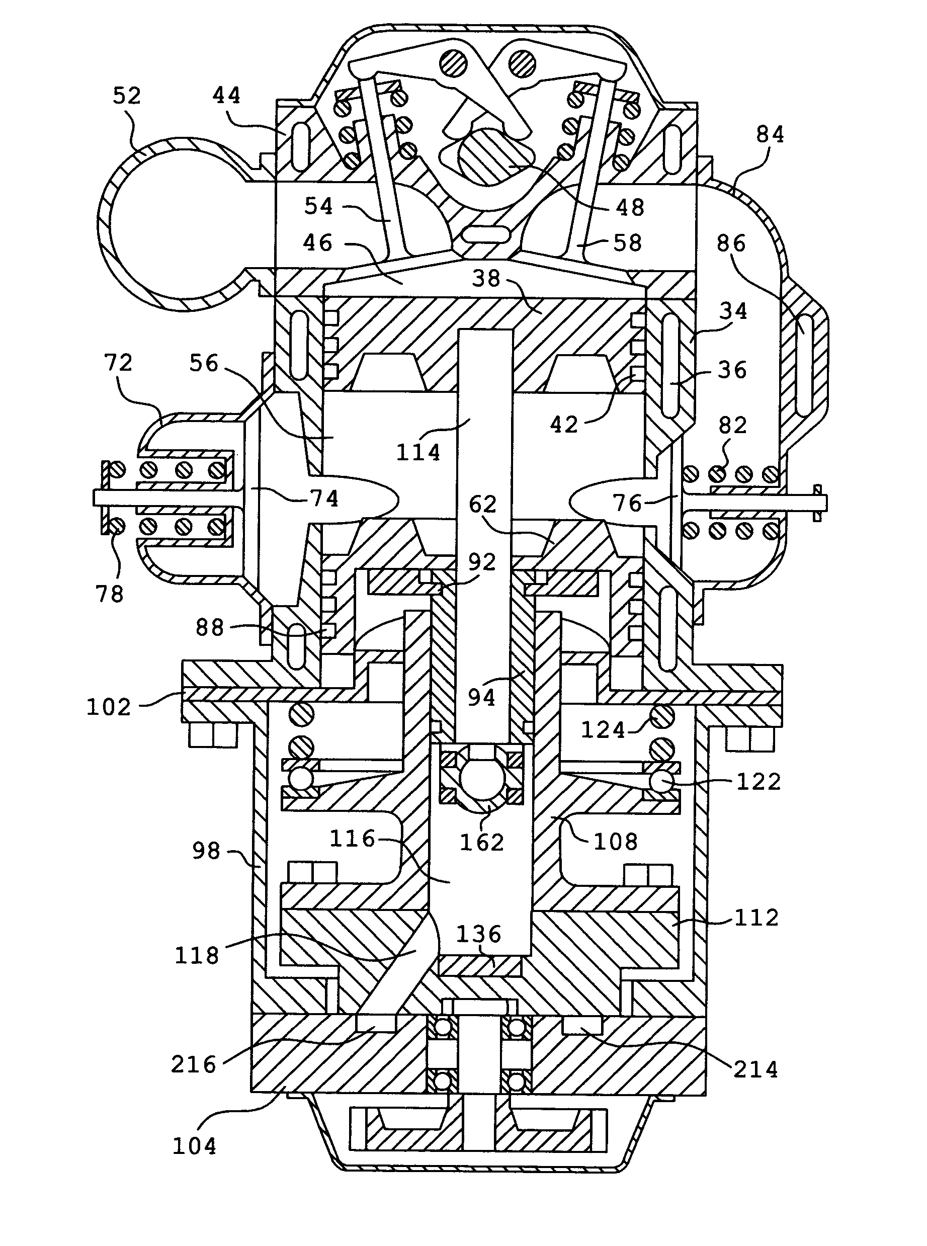
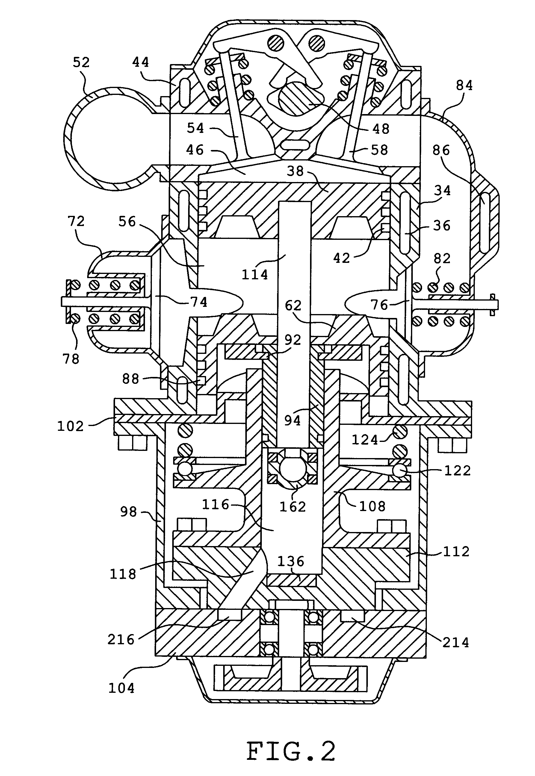
[0044] In accordance with the present invention a hybrid two cycle engine, compressor and pump, (which we shall refer to simply as “hybrid”) is comprised of a two cycle engine, compressor, pump, synchronize mechanism,
reducer, conventional accessory units and electric
hydraulic control system associated with a conventional
hydraulic motor.
[0046] The compressor is comprised of a piston,
camshaft with lobes and the compressor chamber located between the engine and compressor pistons within the engine cylinder. The compressor is comprised of an intake manifold, intake and output valves with springs, which are located on the side surface of engine cylinder. The output valve is coupled with the air injection valve of the engine by a receiver, which is comprised of a
water jacket and is located on the side surface of engine cylinder. The compressor piston, fastened to a hub, is comprised of rings. The valves of the compressor are connected with rockers, pivotably mounted by axles, and connected with the lobes of the compressor
camshaft. The axles is located on the side surface of engine cylinder.
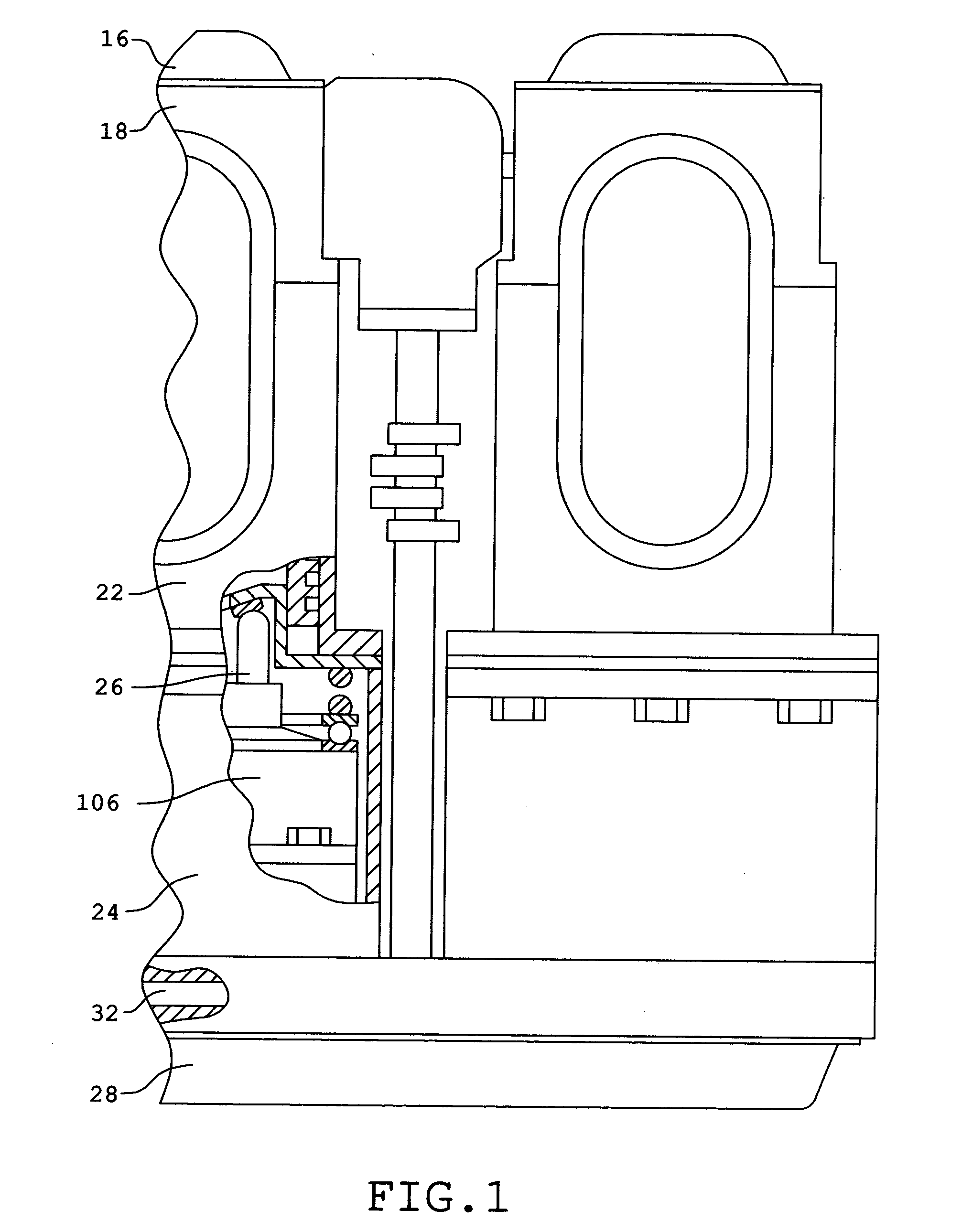
[0047] The pump is comprised of housing, joined to the engine cylinder by a shoe plate, and joined to a valve plate. A rotor is comprised of a
cylinder block fastened to an
abutment and a plunger fastened to the engine piston. The rotor has a
pump chamber with a canal and the plunger, rotor, compressor piston, hub are located coaxially. The rotor is coupled with the shoe plate by a bearing with a spring. The valve plate connected to each rotor by a pump inlet and outlet slots, forming the circumference, and coupled with the
pump chamber by the rotor canal. The hybrid pump associated with the hydrostatic transmission conventional motor by pump outlet and inlet lines.
[0046] The compressor is comprised of a piston, camshaft with lobes and the compressor chamber located between the engine and compressor pistons within the engine cylinder. The compressor is comprised of an intake manifold, intake and output valves with springs, which are located on the side surface of engine cylinder. The output valve is coupled with the air injection valve of the engine by a receiver, which is comprised of a
water jacket and is located on the side surface of engine cylinder. The compressor piston, fastened to a hub, is comprised of rings. The valves of the compressor are connected with rockers, pivotably mounted by axles, and connected with the lobes of the compressor camshaft. The axles is located on the side surface of engine cylinder.
[0049] The
reducer case is the valve plate and is comprised of bearings and shafts, which are connected to the rotors by toothed clutches, gearwheels, and the camshaft of the compressor. The camshaft of the compressor is connected with a gearwheel of a conic reducer, which has a second gearwheel with a shaft connected with the engine camshaft.
[0050] The accessory regular units, cooling system pump, electric
system generator, replenishing pump of hydrostatic transmission, and a
diesel injection pump are located on the valve plate and the shafts of the reducer are coupled with the units.
[0051] The electric
hydraulic control system is comprised of a hydraulic
distributor with solenoids. The first line of the
distributor is connected with the pump inlet line by a
check valve, the second line is coupled with a pump outlet line, the third line is coupled with the tank and the fourth line of the distributor is coupled with the electric manometer, pneumohydraulic accumulator and a starter pump, which comprises of a pedal.
[0052] There has thus been outlined, rather broadly, some features of the invention in order that the detailed description thereof that follows may be better appreciated. There are, of course, additional features of the invention that will be described hereinafter and which will form the
subject matter of the claims appended hereto.
[0053] In this respect, before explaining at least one embodiment of the invention in detail, it is to be understood that the invention is not limited in its application to the details of construction and to the arrangements of the components set forth in the following description or illustrated in the drawings. The invention is capable of other embodiments and of being practiced and carried out in various ways. Also, it is to be understood that the phraseology and terminology employed herein are for the purpose of description and should not be regarded is limiting.
[0054] As such, those skilled in the art will appreciate that the conception, upon which this disclosure is based, may readily be utilized as a basis for the designing of other structures, methods and system for carrying out the several purposes of the present invention. It is important, therefore, that the claims be regarded as including such equivalent constructions insofar as they do not depart from the spirit and scope of the present invention.
[0055] It is therefore an object of the present invention to provide a new and improved hybrid, which has all the advantages of the prior art systems engine-pump and none of the disadvantages.
[0056] It is another object of the present invention to provide a new and improved hybrid, which may be easily and efficiency manufactured and low price marketed.
[0057] It is an object of the present invention to provide a decrease in weight and installation space, while increasing the two cycle engine and pump power with direct energy transmission from engine piston to pump plunger and to compressor piston.
[0058] It is a further object of the present invention to provide a less noisy high-power starter, able to
fast start and restart, and an engine which will
shut down at every red traffic light with decreasing fuel consumption, and to enable the engine to start irrespective of the parking time and by
muscle efforts independent of
external energy sources.
[0059] An even further object of the present invention is to provide high-quality balance and to decrease the vibration.
[0060] Even still another object of the present invention is to provide regular accessory systems for the engine and pump, which will reduce the price.
[0061] Lastly it is an object of the present invention to provide a new and improved hybrid for increasing the efficiency and specific power, while minimizing the installation space and fuel consumption necessary in particular for an automobile.
[0044] In accordance with the present invention a hybrid two cycle engine, compressor and pump, (which we shall refer to simply as “hybrid”) is comprised of a two cycle engine, compressor, pump, synchronize mechanism, reducer, conventional accessory units and electric
hydraulic control system associated with a conventional
hydraulic motor.
[0046] The compressor is comprised of a piston, camshaft with lobes and the compressor chamber located between the engine and compressor pistons within the engine cylinder. The compressor is comprised of an intake manifold, intake and output valves with springs, which are located on the side surface of engine cylinder. The output valve is coupled with the air injection valve of the engine by a receiver, which is comprised of a
water jacket and is located on the side surface of engine cylinder. The compressor piston, fastened to a hub, is comprised of rings. The valves of the compressor are connected with rockers, pivotably mounted by axles, and connected with the lobes of the compressor camshaft. The axles is located on the side surface of engine cylinder.
[0047] The pump is comprised of housing, joined to the engine cylinder by a shoe plate, and joined to a valve plate. A rotor is comprised of a
cylinder block fastened to an
abutment and a plunger fastened to the engine piston. The rotor has a
pump chamber with a canal and the plunger, rotor, compressor piston, hub are located coaxially. The rotor is coupled with the shoe plate by a bearing with a spring. The valve plate connected to each rotor by a pump inlet and outlet slots, forming the circumference, and coupled with the pump chamber by the rotor canal. The hybrid pump associated with the hydrostatic transmission conventional motor by pump outlet and inlet lines.
[0048] The synchronize mechanism is comprised of compensate pistons, a lever with pin shoe, yoke and two diametrically opposite axial push rods coupled with the shoe plate by shoes outside of the rotor and with the compensate pistons inside the rotor. The lever is pivotably coupled with the cylinder block by sliders and axle, coupled with lower spherical portion of the plunger by sliders and a crossbar, and coupled with the yoke and the first push rod by the pin shoe. The yoke is pivotably coupled with the
abutment, and the second push rod is coupled with the yoke by a
saddle shoe and with the compressor piston hub by a gland inside of rotor. The abutment has drain bores.
[0049] The reducer case is the valve plate and is comprised of bearings and shafts, which are connected to the rotors by toothed clutches, gearwheels, and the camshaft of the compressor. The camshaft of the compressor is connected with a gearwheel of a conic reducer, which has a second gearwheel with a shaft connected with the engine camshaft.
[0050] The accessory regular units, cooling system pump, electric
system generator, replenishing pump of hydrostatic transmission, and a
diesel injection pump are located on the valve plate and the shafts of the reducer are coupled with the units.
[0051] The electric hydraulic
control system is comprised of a hydraulic distributor with solenoids. The first line of the distributor is connected with the pump inlet line by a
check valve, the second line is coupled with a pump outlet line, the third line is coupled with the tank and the fourth line of the distributor is coupled with the electric manometer, pneumohydraulic accumulator and a starter pump, which comprises of a pedal.

