One-piece resilient stackable hanger

a stackable hanger and resilient technology, applied in the direction of machine supports, other domestic objects, mechanical apparatus, etc., can solve the problems of inconvenient use, inability to easily use multiple cable runs, complicated and cumbersome prior art devices, etc., to achieve efficient and inexpensive support, improve the resistance to adverse bending or twisting, and facilitate the flexing of the legs of the hanger

Inactive Publication Date: 2006-08-29
BEVERLY MFG
View PDF21 Cites 66 Cited by
  • Summary
  • Abstract
  • Description
  • Claims
  • Application Information

AI Technical Summary

Benefits of technology

[0014]The center portion of the hanger has a mounting aperture in a recessed area, which is in a substantially parallel plane to the adjacent coplanar areas, wherein the mounting aperture is adapted to allow a second hanger to be secured and stacked on the first hanger. The mounting aperture in the recessed area is typically about ⅛ inch recessed from the adjacent coplanar areas, which is the same distance as the normal thickness of a supporting structure. The recessed area between the coplanar areas provides additional structural support and resistance to stress of having a second hanger stacked on the first hanger. The recessed area makes the hanger more resistant to adverse bending or twisting, but assists in the flexing of the legs of the hanger. Also, the recessed area allows the mounting aperture to be coplanar with the recessed area.
[0015]The present invention overcomes the need for assembly of more than one part during both the manufacture of the one-piece, resilient, stackable hanger and during installation of the cable secured by the one-piece hanger. Numerous cables can be supported efficiently and inexpensively using one-piece, resilient, stackable hangers of the present invention.

Problems solved by technology

One of the shortcomings with certain hangers is that they cannot be readily used with multiple runs of cable.
Other prior art devices are complicated and cumbersome and are inconvenient, awkward, and difficult to manufacture, handle and operate.

Method used


Image

  • One-piece resilient stackable hanger
  • One-piece resilient stackable hanger
  • One-piece resilient stackable hanger

Examples


Embodiment Construction

[0021]While the present invention will be described fully hereinafter with reference to the accompanying drawings, in which a particular embodiment is shown, it is to be understood at the outset that persons skilled in the art may modify the invention herein described while still achieving the desired result of this invention. Accordingly, the description that follows is to be understood as a broad informative disclosure directed to persons skilled in the appropriate art and not as limitations of the present invention.

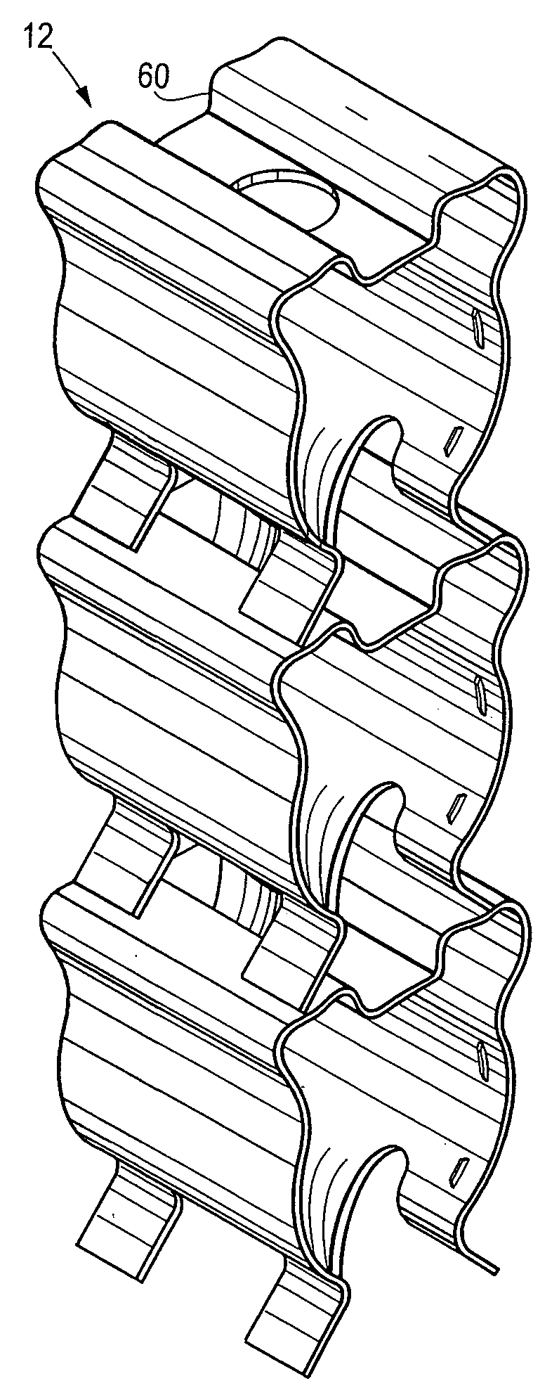
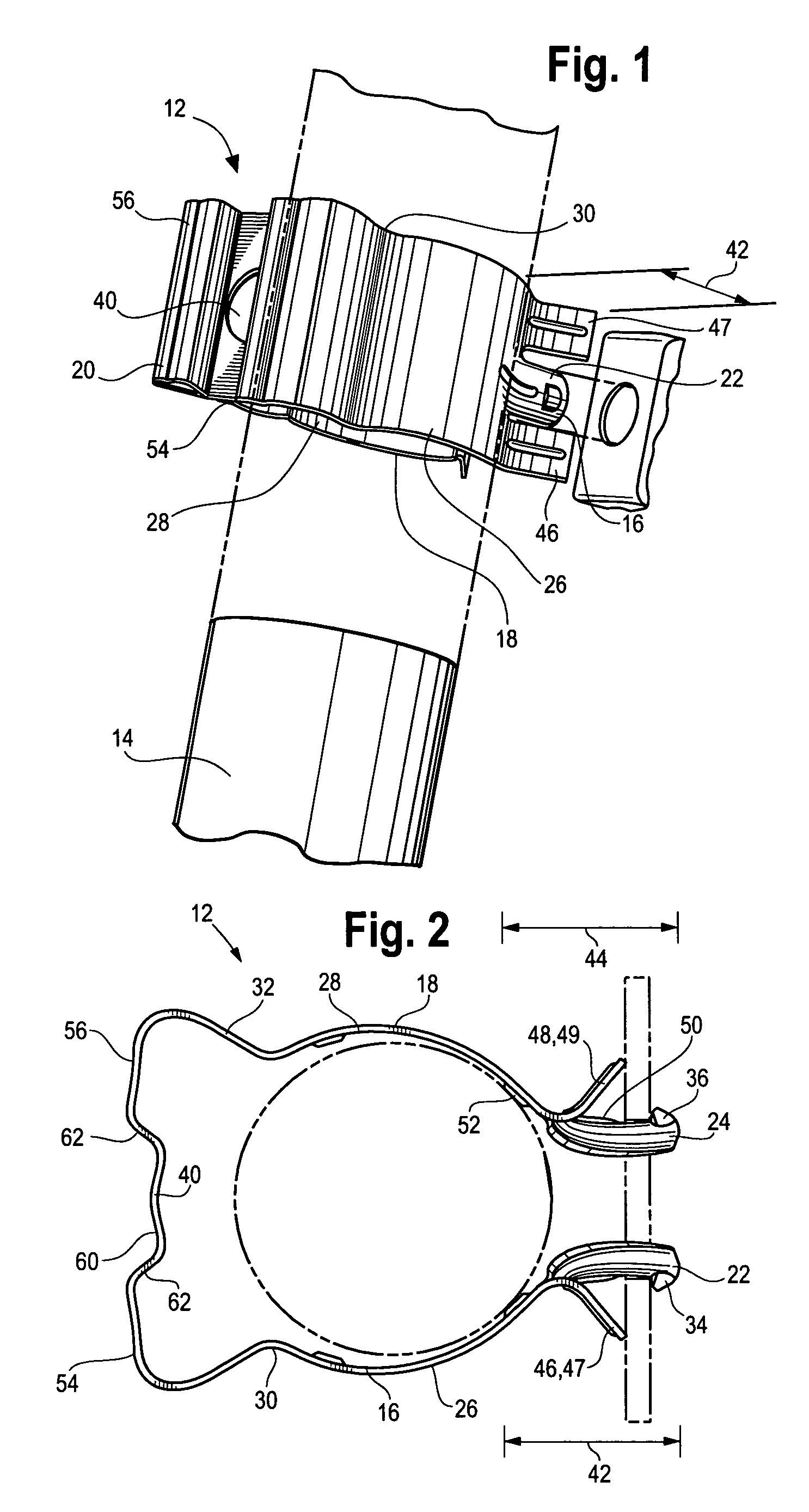
[0022]In the Figures, like reference numerals indicate the same elements throughout. FIG. 1 shows a one-piece, resilient, stackable hanger 12 that can be used to attach cable 14 or the like to a supporting structure, such as a tower. Although shown as horizontal attachments, hangers may be mounted vertically or otherwise. Normally hangers are attached every few feet to secure cable so that numerous hangers are used on a tower. By way of illustration, the hanger 12 supp...


PUM


Abstract

A one-piece, resilient, stackable hanger, which is preferably substantially U-shaped, adapted to attach a cable to a substantially flat surface defining an aperture. The hanger supports cable in a straddling relationship when snapped into an aperture of a supporting structure or another complementary hanger. The hanger has spaced-apart legs extending from the center portion. The center portion has two coplanar areas to provide a base for second hanger being stacked on the first hanger. The center portion has a mounting aperture in a recessed area, which is between the two adjacent coplanar areas, wherein the mounting aperture is adapted to allow a second hanger to be secured and stacked on the first hanger. The stackable hanger can straddle a cable and be easily installed by hand by squeezing, inserting, and snapping into an aperture to support the cable.

Description

BACKGROUND OF THE INVENTION[0001]The present invention relates to a one-piece, resilient, stackable hanger adapted to secure cable to substantially flat supporting structures that define an aperture, such as a cross bar of an antenna tower, or another stackable hanger. The stackable hanger can straddle a cable and be easily installed by hand by squeezing, inserting, and snapping into an aperture to support the cable.[0002]Hangers are known to attach cable or waveguides to a supporting structure, such as antenna systems and towers. Numerous hangers hold cable to supporting structures and are removably mounted in apertures, which are typically 0.75 inch. Hangers have been developed from one piece to ease installation with only one hand. Great advantages are derived from avoiding mounting hardware and tools. Prior one-piece hangers can be installed by hand and do not require additional hardware.[0003]One type of hanger that can be attached to an antenna tower is shown in expired U.S. P...

Claims


Application Information

Patent Timeline
Patent Type & Authority Patents(United States)
IPC IPC(8): F16L3/22
CPCF16L3/12H02G3/30F16L3/222F16L3/221
Inventor SCHMIDT, FREDERICK
Owner BEVERLY MFG
Why Eureka
Try Eureka