Elevator system

a technology of elevator system and traction force, which is applied in the field of elevator system, can solve the problems of insufficient traction force transmissible between the drive pulley and the flat-belt-like traction means, damage to support means, etc., and achieve the effect of increasing the traction capability and high degree of belt transmission operation safety

Active Publication Date: 2005-01-13
INVENTIO AG
View PDF6 Cites 7 Cited by
  • Summary
  • Abstract
  • Description
  • Claims
  • Application Information

AI Technical Summary

Benefits of technology

[0025] The wedge-ribbed belt serving as support means is connected on the side, which faces the guide device of the elevator car at a first support means fixing point with this, extends from this first support means fixing point vertically upwards to the side, which faces the elevator car, of the periphery of the associated drive pulley, loops around the drive pulley by 180° and then runs vertically downwards to a second support means fixing point present at the counterweight. This particularly simple and economic support means arrangement can be realized, in the case of a large ratio between the weights of the full and the empty elevator car, virtually only thanks to the increased traction capability of the wedge-ribbed belt.
[0026] An additional reduction in the dimensions of the drive motor and thus a minimization of the installation space, which is required between the wall of the elevator car at the guide side and the wall of the elevator shaft at the guide side, for the drive can be achieved in that there is installed between the drive output shaft of the drive motor and the drive pulley shaft a belt transmission by which the drive output torque of the drive motor required at the drive output shaft of the drive motor is reduced.
[0027] A high degree of operational safety of the belt transmission with virtually slip-free torque transmission can be achieved if the transmission is realized with a cogged belt or with a wedge-ribbed belt.

Problems solved by technology

However, such elevator systems have certain disadvantages.
As a consequence of the small drive pulley diameter and because, in the case of the use of flat belts as support means known measures for improving traction capability, for example undercutting of the cable grooves at the drive pulleys for round support means, are not usable, the problem can arise in the case of a relatively large weight ratio between fully laden and empty elevating platform or elevator car that the traction forces transmissible between drive pulley and flat-belt-like traction means are not sufficient.
In addition, it is known that in the case of use of flat-belt-like support means without profiling the running surface, significant problems arise with lateral guidance of the support means on the drive pulley and, if they should be present, deflecting rollers and support rollers.
Experience has shown that there is the risk that the support means rubs so strongly against the lateral boundary discs, which are usually present at the drive pulleys, deflecting rollers and support rollers, that the support means are damaged.

Method used


Image

  • Elevator system
  • Elevator system
  • Elevator system

Examples


Embodiment Construction

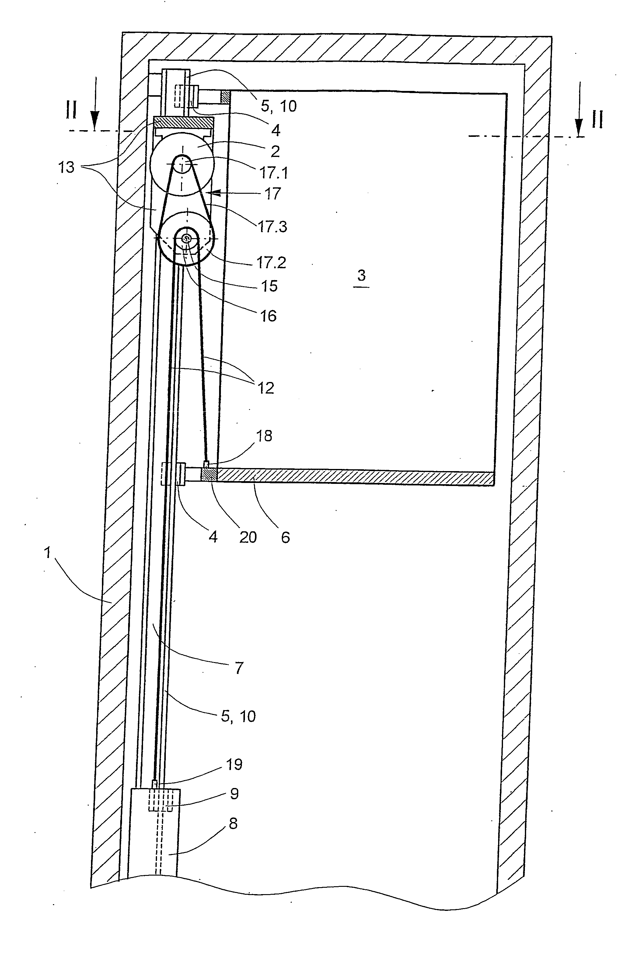
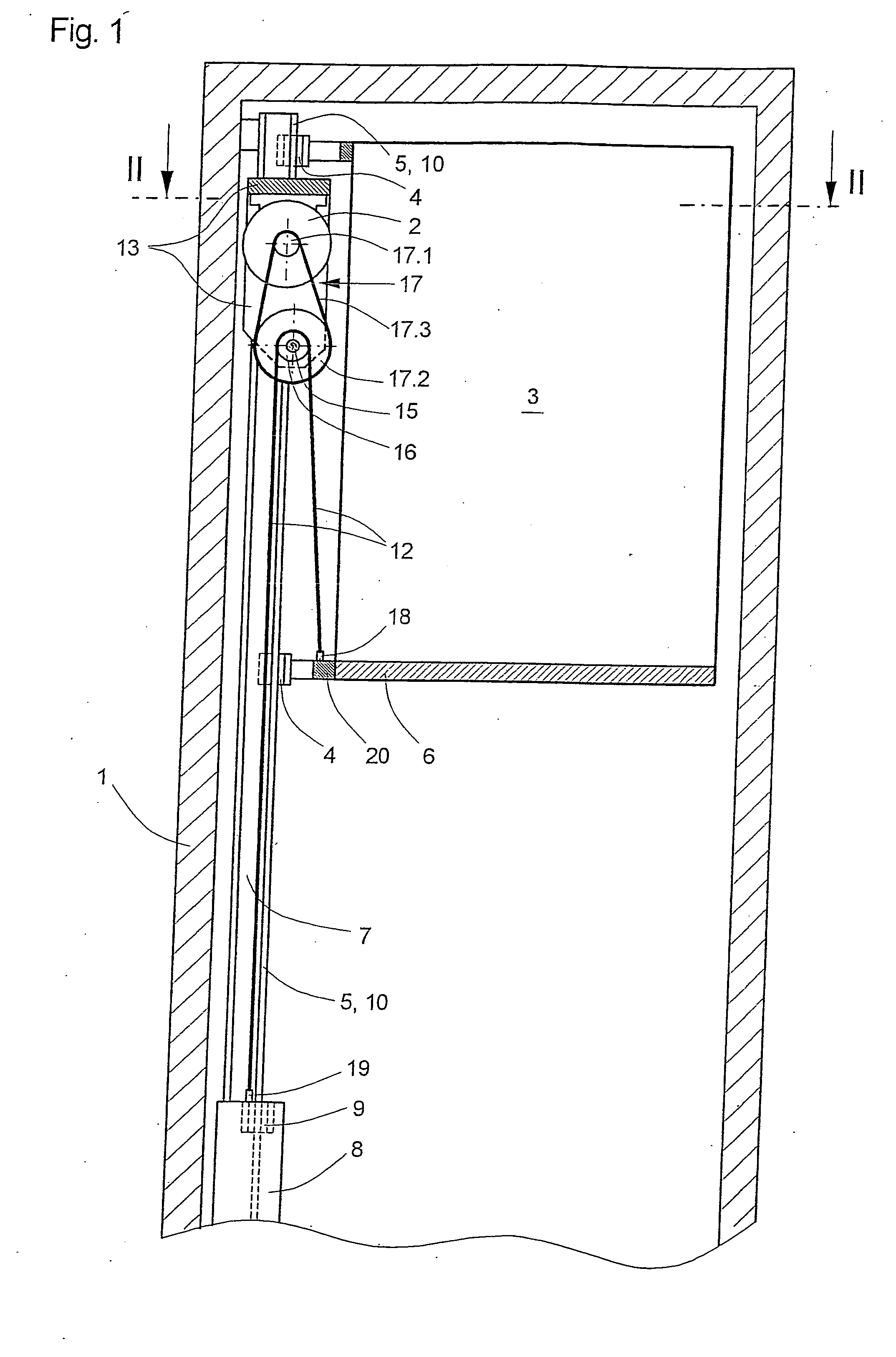
[0033]FIGS. 1 and 2 show an elevator system according to the present invention. FIG. 1 corresponds with a section through the elevator car parallel to its front side. FIG. 2 illustrates a horizontal section, which is taken through the shaft head region, through the elevator system, the position of which is marked in FIG. 1 by the line II-II. An elevator shaft is characterized by reference numeral 1, in which a drive motor 2 moves, by way of a drive pulley 16 and flat-belt-like support means 12, an elevator car 3 of a cantilever mode of construction and a counterweight 8 upwardly and downwardly. The elevator car 3 is guided by means of car guide shoes 4 at two car guide rails 5 and the counterweight 8 is guided by means of counterweight guide shoes 9 at two counterweight guide rails 10. The mentioned guide rails are each part of two vertical guide columns 7, which are fixed laterally of the elevator car 3 in stationary positions in the elevator shaft 1.

[0034] The drive motor 2, pref...


PUM


Abstract

A wedge-ribbed belt supports an elevator car in a cantilevered mode and engages a drive pulley of a drive mounted at the head of an elevator shaft. The belt has a running surface facing the drive pulley with a plurality of ribs and grooves extending in parallel in a longitudinal direction of the belt. The ribs and grooves can be triangular-shaped or trapezium-shaped in cross section. A plane of the drive pulley is arranged vertically and at right angles to a car wall at a counterweight side of the elevator car.

Description

BACKGROUND OF THE INVENTION [0001] The present invention relates to elevator systems having flat belts supporting the elevator car. [0002] Elevator systems of the kind according to the present invention usually include an elevator car and a counterweight which are movable in an elevator shaft or along free-standing guide devices. The guide device for the elevator car in that case consists on the one hand of guide rails which are arranged in a fixed position in the elevator shaft at one side of the elevator car and on the other hand of car guide rails fastened to a side of the elevator car. For producing the movement, the elevator system includes at least one drive with at least one respective drive pulley which by way of support and drive means supports the elevator car and the counterweight and transmits the necessary drive forces to these. [0003] The support means or drive means are termed support means in the following description. [0004] In the case of conventional elevator syst...

Claims


Application Information

Patent Timeline
Patent Type & Authority Applications(United States)
IPC IPC(8): B66B7/06B66B11/00B66B11/04B66B11/08D07B1/22
CPCB66B7/062B66B11/009B66B11/008B66B11/0045
Inventor ACH, ERNST FRIEDRICHBELLO, PABLO CRUZ
Owner INVENTIO AG
Why Eureka
Try Eureka