
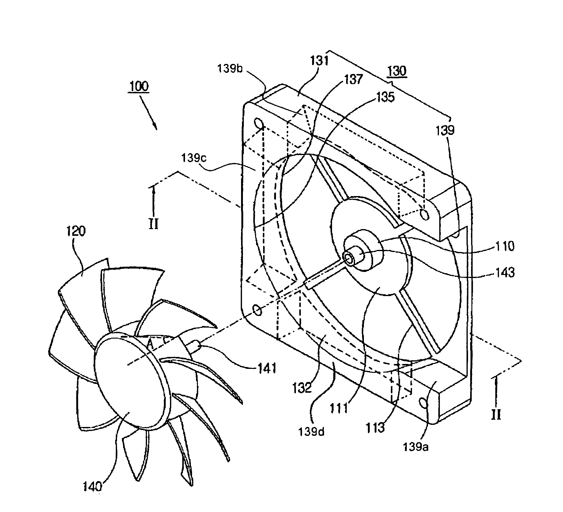
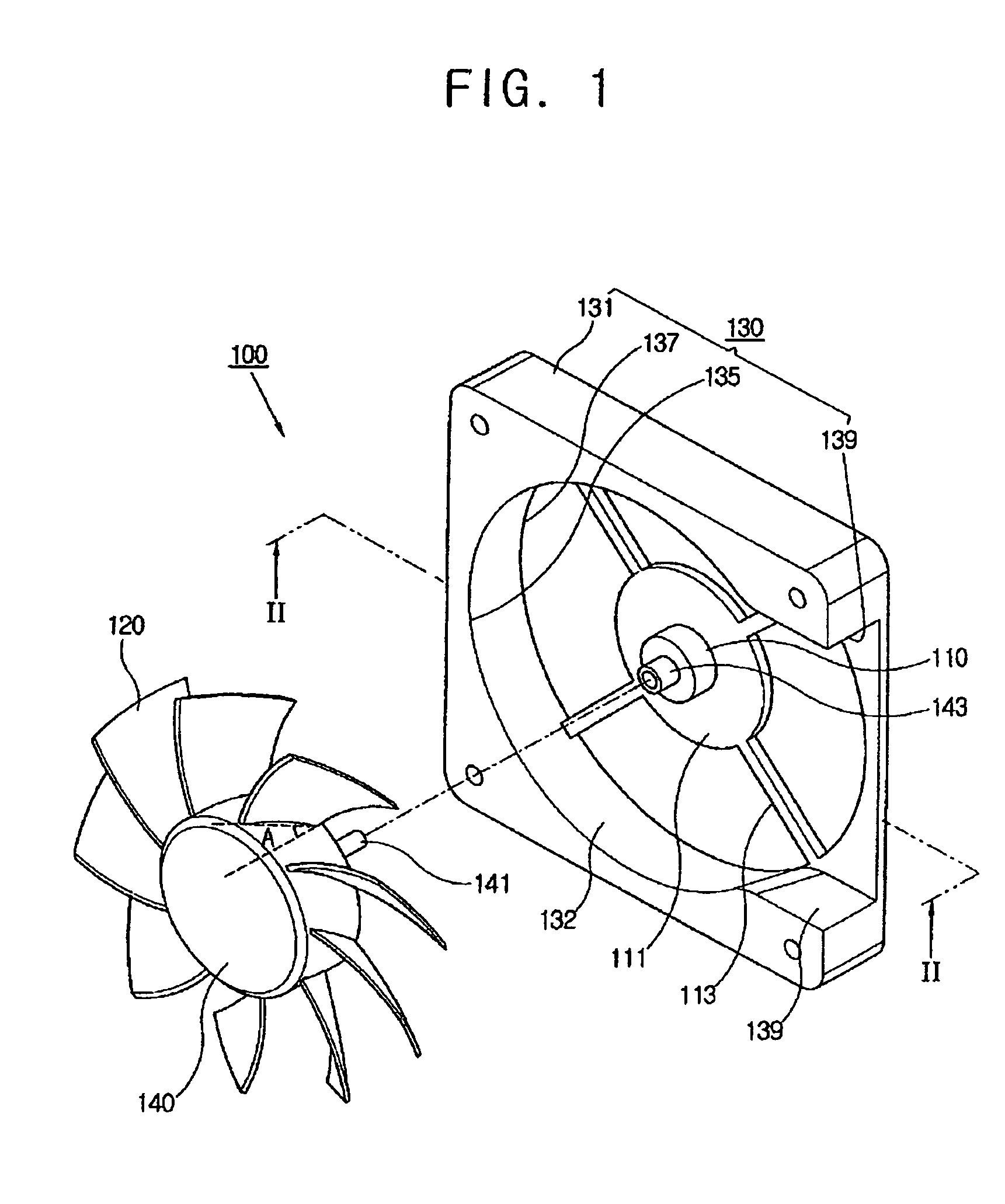
Fan to generate air flow in axial and radial directions

a technology of axial and radial direction and fans, applied in the field of fans, can solve the problems of large installation space and increase noise, and achieve the effects of reducing the number of fans, reducing noise generated, and minimizing the installation space required

Active Publication Date: 2008-04-22
SAMSUNG ELECTRONICS CO LTD
View PDF16 Cites 7 Cited by
  • Summary
  • Abstract
  • Description
  • Claims
  • Application Information

AI Technical Summary

Benefits of technology

The present invention provides a fan that can generate air flow in both axial and radial directions, reducing the number of fans needed for cooling and minimizing installation space and noise. The fan includes a housing with an air inhaler, axial and radial air dischargers, and a display apparatus with a heat sink and fan for cooling. The technical effects of the invention include improved cooling efficiency, reduced installation space requirements, and quieter operation.

Problems solved by technology

However, if using both the axial type fan and the radial type fan, the two fans require a large installation space while noise increases as the two fans are mounted in same apparatus.

Method used


Image

  • Fan to generate air flow in axial and radial directions
  • Fan to generate air flow in axial and radial directions
  • Fan to generate air flow in axial and radial directions

Examples


Embodiment Construction

[0026]Reference will now be made in detail to the embodiments of the present general inventive concept, examples of which are illustrated in the accompanying drawings, wherein like reference numerals refer to the like elements throughout. The embodiments are described below in order to explain the present general inventive concept by referring to the figures.

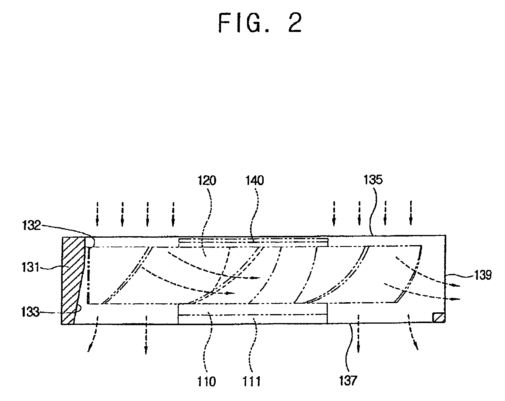
[0027]As illustrated in FIGS. 1 and 2, a fan 100 according to an embodiment of the present general inventive concept comprises a driving motor 110, a plurality of blades 120 that are connected to the driving motor 110 to rotate therewith and create an air flow, a housing 130 having a housing main body 131 to accommodate the driving motor 110 and the blades 120, an air inhaler 135 which is provided in the housing main body 131 to inhale air toward the blades 120, an axial air discharger 137 which is provided in a direction of a rotational axis (axial direction) of the blades 120, and a radial air discharger 139 which is provided ...


PUM


Abstract

A fan including a driving motor, a plurality of blades which are connected to the driving motor to rotate, and a housing having a housing main body to accommodate the driving motor and the blades, an air inhaler that is provided in the housing main body to inhale air toward the plurality of blades, an axial air discharger that is provided in a rotational axis direction of the plurality of blades and a radial air discharger that is provided in a radial direction substantially perpendicular to the rotational axis. The fan generates air flow both in the axial and radial directions, thereby increasing the number of directions in which air flows, reducing the number of fans to be used, minimizing an installation space required, and reducing noise generated by the fans.

Description

CROSS-REFERENCE TO RELATED APPLICATIONS[0001]This application claims the benefit under 35 U.S.C. § 119 of Korean Patent Application No. 2005-45116, filed on May 27, 2005, in the Korean Intellectual Property Office, the disclosure of which is incorporated herein in its entirety.BACKGROUND OF THE INVENTION[0002]1. Field of the Invention[0003]The present general inventive concept relates to a fan, and more particularly, to a fan that generates an air flow both in axial and radial directions.[0004]2. Description of the Related Art[0005]Generally, various fans that forcibly ventilate air are used to cool off heat generated from home electronic appliances, such as an air conditioner, a ventilation system and other various electronic appliances.[0006]The fans are classified into axial type fans and radial type fans according to a direction of an air flow generated by the fans. The axial type fans direct the air flow in parallel with a rotational axis, and generate a vast amount of air flow...

Claims


Application Information

Patent Timeline
Patent Type & Authority Patents(United States)
IPC IPC(8): F04B17/00
CPCF04D17/06F04D25/08F04D29/388F04D29/403F04D29/441F04D29/541F04D29/584F04D29/663F05D2210/12Y10S415/00Y10S417/00
Inventor CHO, JIN-HYUN
Owner SAMSUNG ELECTRONICS CO LTD
Learn More