Antenna combined with terminal housing

A technology for terminal shells and antennas, applied to antennas, loop antennas, antenna parts, etc., can solve problems such as changing antenna characteristics, achieve the effect of preventing characteristic changes and minimizing installation space

Inactive Publication Date: 2013-05-01
ACE TECH
View PDF4 Cites 7 Cited by
  • Summary
  • Abstract
  • Description
  • Claims
  • Application Information

AI Technical Summary

Problems solved by technology

Although the antenna connected to the housing reduces the installation space, it has the problem of changing the characteristics of the antenna when the user's hand or head comes into contact with the housing.

Method used


Image

  • Antenna combined with terminal housing
  • Antenna combined with terminal housing
  • Antenna combined with terminal housing

Examples


Embodiment Construction

[0032] Since the present invention allows various changes and various embodiments, specific embodiments will be described with reference to the drawings and the detailed description of the specification. However, this is not intended to limit the present invention to a specific practice mode, and all changes, equivalents and substitutions are included in the present invention without departing from the spirit and technical scope of the present invention. In describing the drawings, the same reference numerals are used to designate the same elements.

[0033] Embodiments of the present invention will be described in detail below with reference to the accompanying drawings.

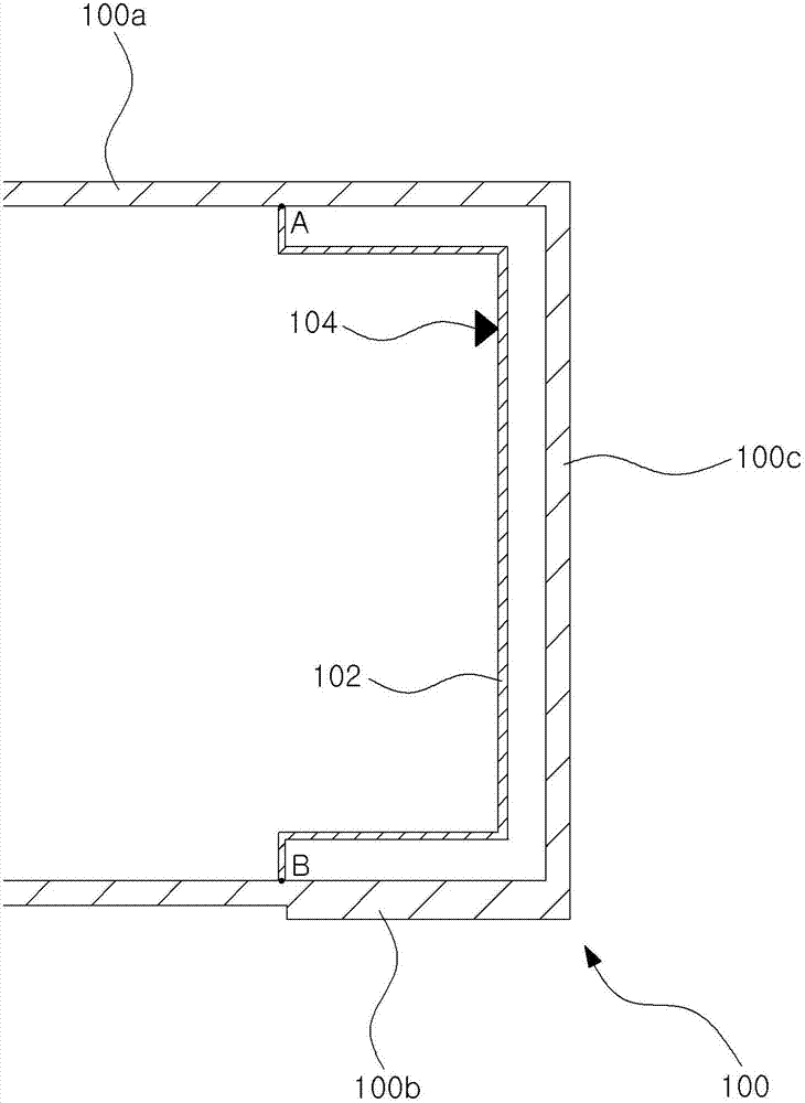
[0034] figure 1 It is a structural view of an antenna connected to a terminal housing according to an embodiment of the present invention. Such as figure 1 As shown, an antenna connected to a terminal housing according to an embodiment of the present invention includes an outer frame radiator 100 , an in...


PUM


Abstract

An antenna combined with a terminal housing is disclosed. The disclosed antenna includes an outer frame radiator, which is joined to a side wall of the terminal housing, and an inner frame radiator, which has one end joined to a first point on the outer frame radiator and the other end joined to a second point on the outer frame radiator, and which forms a loop by joining the outer frame radiator, where a feed signal is provided to the inner frame radiator. The disclosed antenna provides the advantages of preventing property changes caused by contact between a person's body and the terminal, and of minimizing mounting space while maintaining stable characteristics.

Description

technical field [0001] Embodiments of the present invention relate to an antenna for transmitting and receiving signals, and in particular to an antenna disposed inside a terminal. Background technique [0002] At present, the mobile communication terminal technology not only requires a terminal to provide multiple services, but also provides more and more developed services. [0003] Today's mobile communication terminals represented by smartphones require not only communication functions but also functions of small computers, and at the same time, their structures are becoming smaller and lighter. [0004] With the diversification of functions and lightness of structure of mobile communication terminals, the installation space of antennas for transmitting and receiving signals is required to become smaller. However, due to the demand for broadband and multi-band broadband capabilities, the space that can be reduced by antennas is limited. [0005] Generally speaking, the ...

Claims


Application Information

Patent Timeline
Patent Type & Authority Applications(China)
IPC IPC(8): H01Q1/36H01Q1/22
CPCH01Q1/36H01Q1/243H01Q7/00H01Q1/22H01Q1/24
Inventor 郑钟镐
Owner ACE TECH
Why Eureka
Try Eureka