Liquid ejecting head and liquid ejecting apparatus

a liquid ejector and liquid technology, applied in printing and other directions, can solve problems such as problems not only in the ink jet recording head but also in the liquid ejector

Active Publication Date: 2017-06-20
SEIKO EPSON CORP
View PDF17 Cites 4 Cited by
  • Summary
  • Abstract
  • Description
  • Claims
  • Application Information

AI Technical Summary

Benefits of technology

[0011]In this case, the cantilever is provided, and thereby it is possible to prevent the compliance region of the flexible member from being rapidly deformed in deflection in an initial stage of the pressure fluctuation in the manifold and the compliance region can absorb the pressure fluctuation in the manifold. Accordingly, it is possible to prevent variations in ejection characteristics of a liquid and, particularly in the weight of the liquid in an initial stage of and during the pressure fluctuation in the manifold. In addition, the cantilever is provided, and thereby it is possible to prevent the compliance region of the flexible member from adhering to the cap member such that it is possible to prevent malfunction due to adherence of the flexible member to the cap member.Aspect 2
[0012]In the liquid ejecting head according to Aspect 1, it is preferable that the frame-like member has a first notch provided on a surface facing the cap member, in which the surface of the frame-like member on the cantilever side from the first notch on the surface thereof facing the cap member becomes the unfixed region. In this case, the first notch is provided in the frame-like member, and thereby it is possible to prevent the adhesive, with which the frame-like member and the cap member adhere to each other, from flowing out to the cantilever side from the first notch such that it is possible to form the unfixed region with ease and high accuracy.Aspect 3
[0013]In the liquid ejecting head according to Aspect 1 or 2, it is preferable that the cantilever has a thickness which is thinner on the distal end side than on the support point side in a direction in which the compliance region faces the cap member. In this case, the cantilever is thinner on the distal end side, and thereby it is possible to prevent the adhesive, with which the frame-like member and the cap member adhere to each other on the distal end side, from flowing out such that it is possible to form the unfixed region on the distal end side of the cantilever with ease and high accuracy.Aspect 4
[0016]In the liquid ejecting head according to any one of Aspects 1 to 5, it is preferable that a flow path member defining a wall surface of the manifold is an opening in a surface of the flow path member, which faces the cantilever, the opening defining the manifold is fixed to the flexible member such that the opening is positioned on the support point side from the distal end side of the cantilever. In this case, since the frame-like member can receive a load produced when the flow path member is joined to the flexible member and the frame-like member, it is possible to reliably perform the joining between the flow path member and the flexible member. Accordingly, it is possible to prevent a gap from being generated due to an insufficient load when the flow path member is joined to the flexible member, and to prevent a defect such as bubbles being caught from occurring.Aspect 7
[0017]In the liquid ejecting head according to any one of Aspects 1 to 6, it is preferable that the liquid ejecting head further includes: an island-like member disposed in the compliance region to be apart from the frame-like member, between the flexible member and the cap member, in which a surface of the island-like member, which faces the flexible member, is fixed to the flexible member and a surface of the island-like member on the side facing the cap member is not fixed to the cap member. In this case, the island-like member is provided, and thereby it is possible to prevent the compliance region of the flexible member from adhering to the cap member. In addition, the island-like member is not fixed to the cap member, and thereby it is possible to prevent the deformation of the compliance region to the manifold side from being regulated such that the compliance region can reliably perform the absorption of the pressure fluctuation in the manifold.Aspect 8
[0023]In this case, it is possible to realize the liquid ejecting apparatus in which the compliance region absorbs the pressure fluctuation of the liquid in the manifold, variations in the liquid ejection characteristics due to the pressure fluctuation is prevented, and the compliance region is prevented from adhering to the cap member.

Problems solved by technology

However, a problem arises in that, when rapid deflection of the compliance region is performed in an initial stage from a print stand-by state in which ink is not ejected to the time when ejection of the ink is started, that is, when the printing is started, variations in ejection characteristics of the ink in the initial stage, and particularly in the ink weight, will occur in a state in which the manifold is filled with the ink during a printing operation such that smooth deflection of the compliance region occurs, and deformation is performed in a deflection direction by the ink consumed.
Further, such problems arise not only in the ink jet-type recording head but also similarly in a liquid ejecting apparatus that ejects a liquid except for the ink.

Method used


Image

  • Liquid ejecting head and liquid ejecting apparatus
  • Liquid ejecting head and liquid ejecting apparatus
  • Liquid ejecting head and liquid ejecting apparatus

Examples


embodiment 1

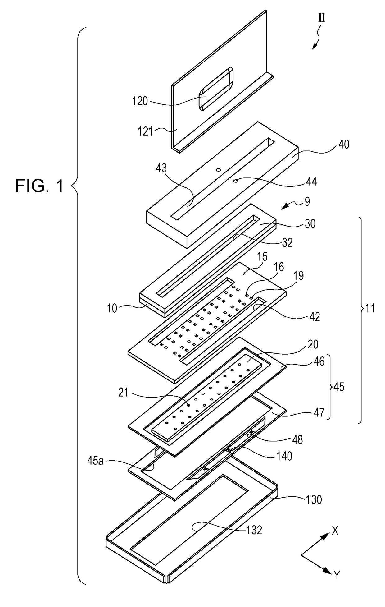
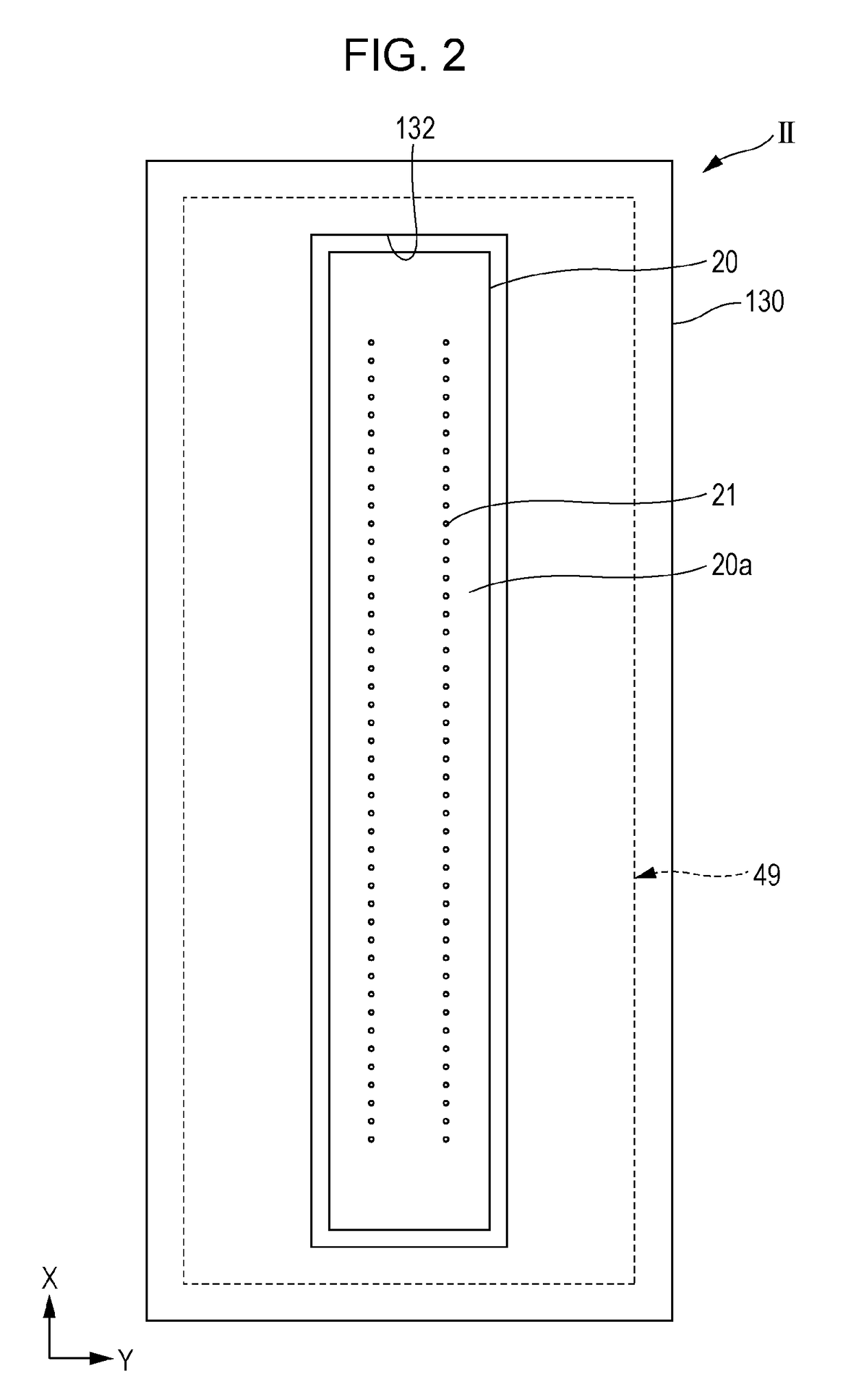
[0047]FIG. 1 is an exploded perspective view illustrating an ink jet-type recording head as an example of a liquid ejecting head according to Embodiment 1 of the invention. FIG. 2 is a plan view illustrating the ink jet-type recording head. In addition, FIG. 3 is a plan view illustrating a compliance substrate and FIG. 4 is a sectional view illustrating the recording head taken along line IV-IV in FIG. 3. FIG. 5 is an enlarged sectional view illustrating main components in FIG. 4.

[0048]As illustrated in the FIG. 1 to FIG. 4, the ink jet-type recording head II (hereinafter, also simply referred to as a recording head II) includes a plurality of members such as a head main body 11, a case member 40 fixed to one surface side of the head main body 11, a cover head 130 fixed to the other surface side of the head main body 11. In addition, the head main body 11 of Embodiment 1 includes a flow path formation substrate 10, a communicating plate 15 provided on one surface side of the flow pa...

embodiment 2

[0094]FIG. 11 is an enlarged sectional view illustrating the main components of the ink jet-type recording head according to Embodiment 2 of the invention. FIG. 12 is an enlarged sectional view illustrating the main components of the ink jet-type recording head according to Embodiment 2 of the invention. Further, the same reference sighs are assigned to the same members as in the Embodiment 1 described above and repetitive description is omitted.

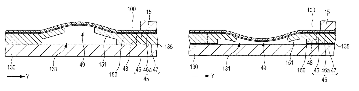
[0095]As illustrated in FIG. 11, the cantilevers 150 are provided in the compliance space 131 between the flexible member 46 and the cover head 130. A first notch 151 is provided between the support point side and the distal end side on the surface of the cantilever 150, which faces the cover head 130. In this manner, although the cantilever 150 has both side of the first notch 151, that is, the support point side and the distal end side which are formed to have the same thickness, it is possible to prevent the adhesive 135, with which the f...

embodiment 3

[0097]FIG. 13 is an enlarged sectional view illustrating the main components of the ink jet-type recording head according to Embodiment 3 of the invention. Further, the same reference sighs are assigned to the same members as in the Embodiments 1 and 2 described above and repetitive description is omitted.

[0098]As illustrated in FIG. 13, the frame-like member 47 has the cantilever 150 having the same thickness as the frame-like member 47. In addition, a second notch 136 is provided in a surface of the cover head 130, which faces the cantilevers 150. The second notch 136 is disposed to be separated from the cover head 130 and the cantilevers 150. Also, the second notch 136 is provided, and thereby it is possible to prevent the adhesive 135, with which the frame-like member 47 and the cover head 130 adhere, from flowing over the cantilevers 150 facing the second notch 136. In other words, the portion of the cantilevers 150, which faces the second notch 136, becomes the unfixed region ...


PUM


Abstract

A liquid ejecting head includes: a plurality of pressure generating chambers communicating with nozzles through which a liquid is ejected; a manifold communicating with the plurality of pressure generating chambers; a flexible member that has a surface on one side which defines at least a part of a wall of the manifold, that has a surface on the other side, on which an adhesive layer is formed, and that has a compliance region, which is able to perform deflection in response to pressure fluctuation in the manifold, in a region in which the adhesive layer is formed; a compliance space disposed on a side opposite to the manifold through the flexible member; a cap member facing the flexible member through the compliance space; and a frame-like member that is disposed between the flexible member and the cap member and has a cantilever, in which the cantilever is fixed to at least a part of the flexible member of the compliance region and has an unfixed region which is not fixed to the cap member on the distal end side thereof.

Description

[0001]The entire disclosure of Japanese Patent Application No: 2015-023499, filed Feb. 9, 2015 is expressly incorporated by reference herein in its entirety.BACKGROUND[0002]1. Technical Field[0003]The present invention relates to a liquid ejecting head that ejects a liquid from a nozzle and a liquid ejecting apparatus, and particularly to an ink jet-type recording head that ejects ink as the liquid and an ink jet-type recording apparatus.[0004]2. Related Art[0005]As an ink jet-type recording head which is a representative example of a liquid ejecting head that ejects a droplet, there is a recording head which includes a nozzle and a flow path such as a pressure generating chamber communicating with the nozzle, and in which a pressure generator causes pressure in ink in the pressure generating chamber to be changed such that an ink droplet is discharged from the nozzle.[0006]According to the ink jet-type recording head, there has been proposed a recording head in which a so-called co...

Claims


Application Information

Patent Timeline
Patent Type & Authority Patents(United States)
IPC IPC(8): B41J2/055B41J2/175B41J2/14
CPCB41J2/055B41J2/14233B41J2/175B41J2002/14241B41J2002/14266B41J2002/14419B41J2/14201B41J2/16505
Inventor KANEGAE, TAKAHIRO
Owner SEIKO EPSON CORP
Why Eureka
Try Eureka