Lighting device

a technology of light source and light source, which is applied in the direction of semiconductor devices, light source lighting and heating apparatus, coatings, etc., can solve the problems of reducing optical efficiency, undesired light rings, and provoking drawbacks

Active Publication Date: 2017-09-28
ARTEMIDE
View PDF8 Cites 0 Cited by
  • Summary
  • Abstract
  • Description
  • Claims
  • Application Information

AI Technical Summary

Benefits of technology

The patent text describes the technical effects of a lighting device that has high efficiency and eliminates light defects. The device has a source that emits light rays that reflect back into the device, resulting in a single reflection. This ensures that all the light rays leave the device without any loss of efficiency. Additionally, the use of LED light sources reduces the possibility of light defects.

Problems solved by technology

the facets arranged in a radial manner, in order to distribute the light far from the axis and, hence, widen the light beam emitted, must have a very marked curvature (short bending radius), but, in this way, the light reflected by the facets can be redirected into the reflector (instead of being projected outwards), thus causing secondary reflection that can cause dazzling and reduce the optical efficiency.
Furthermore, if the projector uses a LED light source, which is becoming more and more common, you can typically experience the projection of undesired light rings onto a working surface lit by the projector.
As a consequence, the further drawback can arise consisting in the projection of yellowish areas (spots) on a white background.
These irregularities, which usually do not jeopardize optical performances, can though create an undesired effect, making the reflector “bright” (lit up).

Method used


Image

  • Lighting device
  • Lighting device
  • Lighting device

Examples


Embodiment Construction

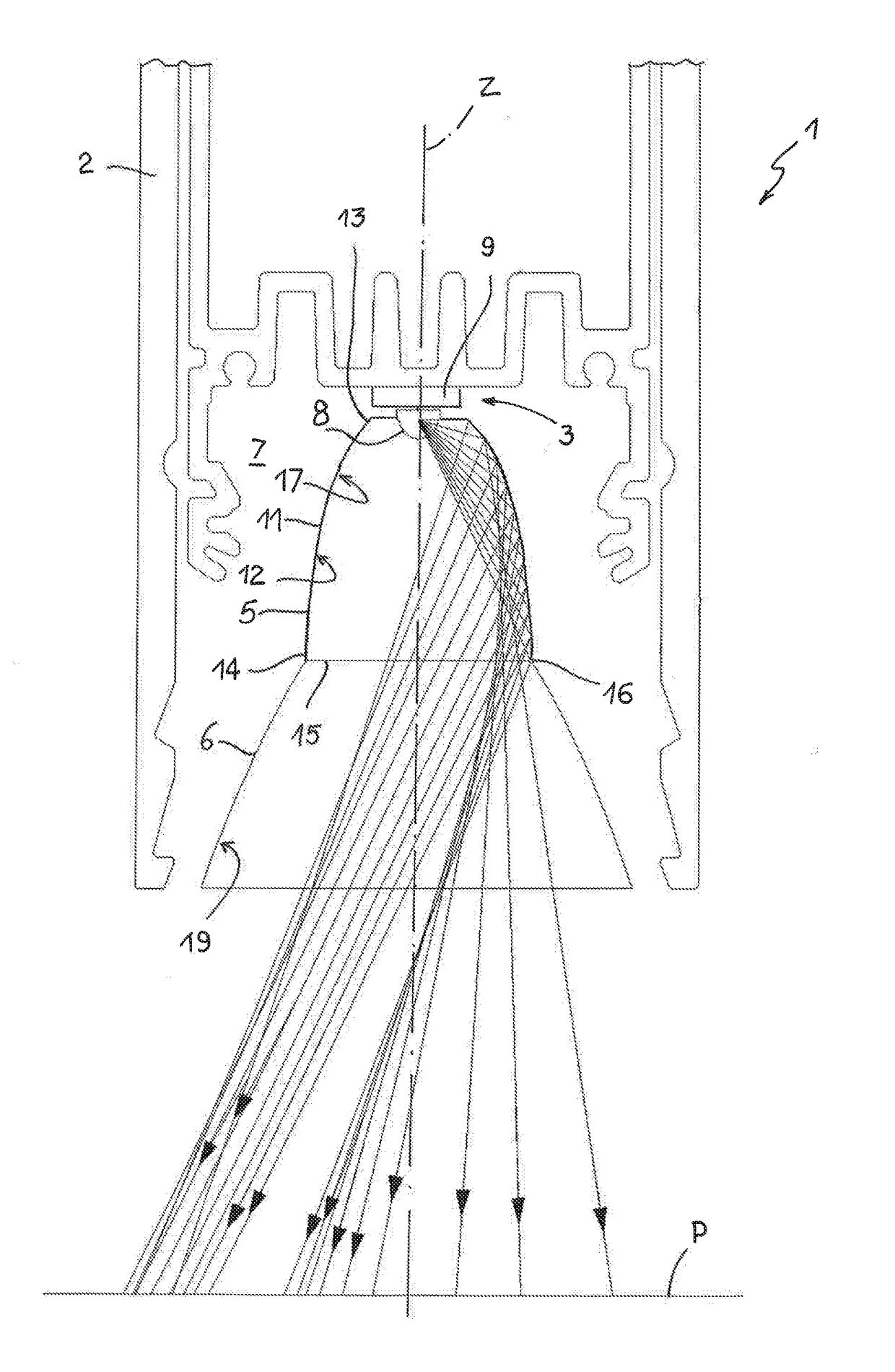
[0024]In FIG. 1, number 1 indicates, as a whole, a lighting device (light projector), in particular a LED lighting device, for the illumination of objects and / or rooms, for example to light a working surface P.

[0025]The device 1 comprises a support structure 2, at least one light source 3, a reflector 5 and, optionally, a shield 6.

[0026]The support structure 2, which is only schematically and partially shown in FIG. 1, can have different shapes, also based on the purpose of the device (which can be used as a suspension lamp, a floor lamp, etcetera). In the non-limiting example shown herein, the support structure 2 is longitudinally elongated and bar-shaped, and has an inner compartment 7, which houses the light source 3, the reflector 5 and possibly the shield 6.

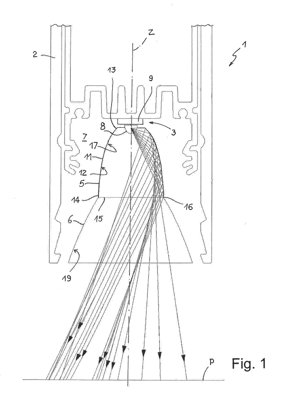
[0027]The light source 3 is, in particular, a LED light source comprising one or more LEDs 8 carried by a support 9.

[0028]The reflector 5 extends along and around a longitudinal axis Z, which also defines an optical axis of ...


PUM

PropertyMeasurementUnit
Angleaaaaaaaaaa
Shapeaaaaaaaaaa
Reflectionaaaaaaaaaa

Abstract

A lighting device, in particular a LED lighting device, comprises at least one light source and a reflector extending along and around a longitudinal axis and having an internal reflective surface arranged so as to intercept at least part of the light emitted by the light source and reflect said part towards a light exit opening; the internal reflective surface is a faceted polynomial surface.

Description

PRIORITY CLAIM[0001]This application claims priority from Italian Patent Application No. 102016000031730 filed on Mar. 25, 2016, the disclosure of which is incorporated by reference.TECHNICAL FIELD[0002]The invention relates to a lighting device, in particular a LED lighting device, which is suitable to be used as a light projector for the illumination of objects and / or rooms.BACKGROUND OF THE INVENTION[0003]In the lighting field and, in particular, in the field of light projectors (lighting apparatuses that, by means of optical elements such as mirrors or lenses, project an intense light beam with a great capacity, which is emitted by a light source, so as to light objects and / or rooms), parabolic reflectors are largely used, namely reflectors having a parabolic cross section and obtained from a parabolic profile which, by rotating around its axis, generates a paraboloid of revolution.[0004]By placing a light source in the focus of the rotation solid obtained by so doing (parabolic...

Claims


Application Information

Patent Timeline
IPC IPC(8): F21V7/04F21V7/22F21V19/00F21V11/00
CPCF21V7/04F21V11/00F21Y2115/10F21V19/003F21V7/22F21V7/048F21V7/28
Inventor DE BEVILACQUA, CARLOTTA FRANCESCA ISOLINA MARIAFRANZOSI, ROBERTO EFREM
Owner ARTEMIDE
Why Eureka
Try Eureka