
Method for filtering a fingerprint image continuation-in-part

Inactive Publication Date: 2008-06-19
BICHIGOV VLADIMIR NICKOLAEVICH +3
View PDF13 Cites 3 Cited by
  • Summary
  • Abstract
  • Description
  • Claims
  • Application Information

AI Technical Summary

Benefits of technology

[0020]The object of the present invention is to provide a method for fingerprint image filtering, that provides effective image processing of high-curvature regions.
[0022]As a result, high-curvature regions of the fingerprint lines can be filtered without loss of efficiency.

Problems solved by technology

Low quality of fingerprints may lead to erroneous image comparison.
Current methods of filtration are only effective for where the curvature of fingerprint lines is low, and ineffective for filtering high-curvature regions.
In this case the filter can only be aligned with the line along a short line section, whereas the rest of the line is oriented differently, and this affects the results of filtration.
Filtration of such regions may result in that false elements emerge on the image, while true elements are lost.
However errors in the estimation of orientation distorts the image and results in loss of true minutiae or creation of spurious minutiae.
It is usually not possible to estimate orientation correctly neither in the low quality nor in the high-curvature regions of the image.
Further, analyzing experimental testing of this method, Erol et al. concludes that high-curvature regions of fingerprint lines shows unacceptably low certainty.
This results in degradation of filtering efficiency and even incapability to distinguish fingerprint lines in these regions.
Thus, Erol et al. merely provide an automatic method for restricting filtering degree in the regions that are difficult to process, rather than solve the problem of correctly processing high-curvature regions.
This results in decrease of the filter selectivity and, consequently the filter efficiency in the presence of typical artifacts of fingerprint image.

Method used


Image

  • Method for filtering a fingerprint image continuation-in-part
  • Method for filtering a fingerprint image continuation-in-part
  • Method for filtering a fingerprint image continuation-in-part

Examples


Embodiment Construction

[0033]The method for filtering a fingerprint image will be described in more details below.

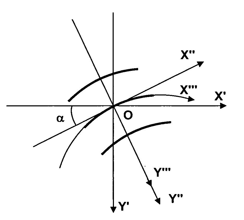
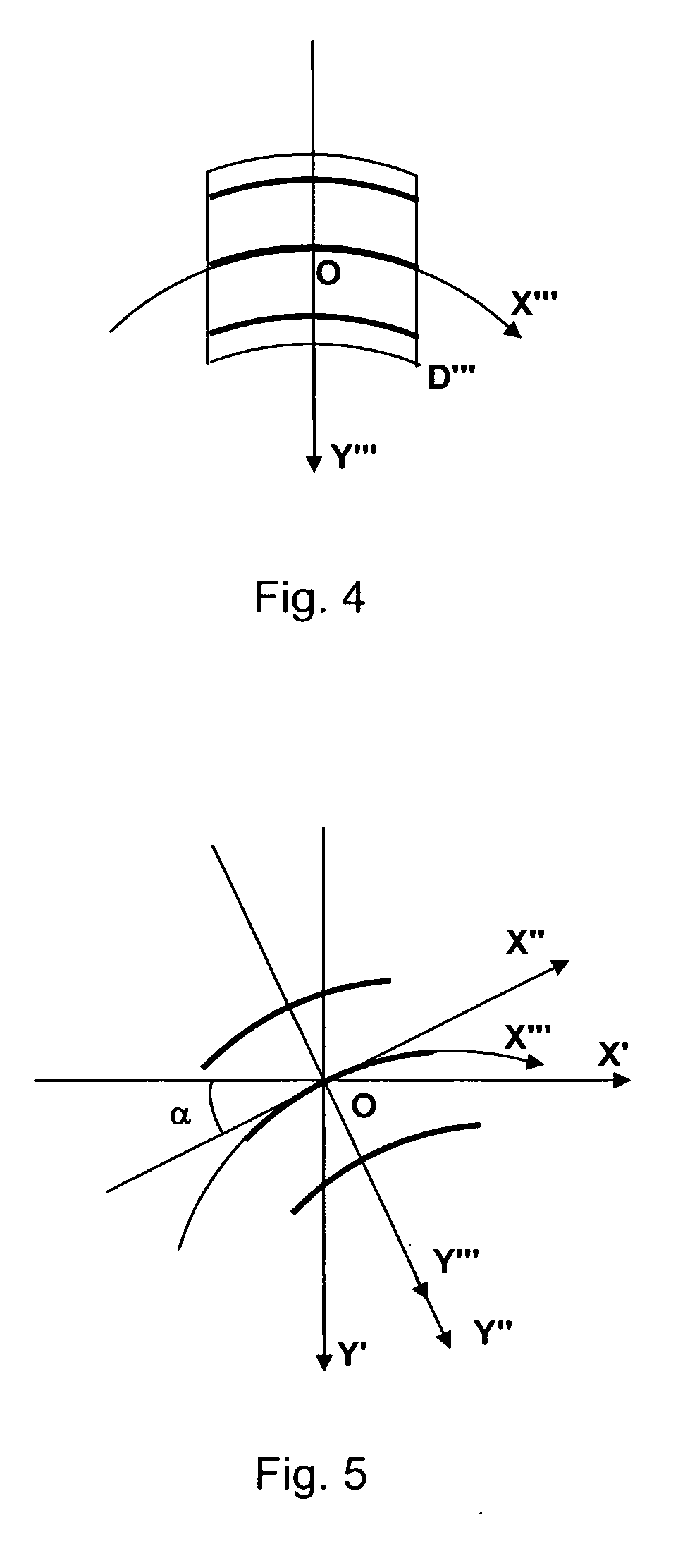
[0034]At the first stage of processing a reference filter F(x, y) is developed using known methods (analytically). The reference filter is optimized for filtering an ideal fingerprint image that consists of horizontal fingerprint lines having constant ridge spacing. The filter, that is determined by the function F(x, y), is developed in the field D as shown in FIG. 1.

[0035]Further steps are to be made sequentially on each point of the processed image.

[0036]In the coordinate system OX′Y′ a neighborhood is chosen for the point O to be processed. The neighborhood shall include several fingerprint ridges. In this neighborhood, local properties of the image are determined. As shown in FIG. 2, the direction of fingerprint lines is determined at each central point of a fingerprint ridge or valley, wherein this direction is assumed to be the direction of line A which is tangent to this fingerprint rid...


PUM


Abstract

The present invention relates to the digital processing of images, and, more particularly, to the digital filtering of fingerprint images. The present invention can be used in criminalistics for fingerprint identification.The object of the present invention is to develop a method for filtering a fingerprint image, that provides effective image processing in the areas where the curvature of fingerprint lines is high.This object is achieved by providing a method for filtering a fingerprint image, the method including the step of sequentially processing areas of the image by a directional filter having at least one central ridge and adapted to local properties of respective areas of the image, the local properties including distance between the ridges, orientation of the fingerprint line, and curvature of the same. Further steps include adapting the filter to the local curvature by curving at least one central ridge of the filter in the plane of spatial coordinates in such a way its curvature is brought into proximity with the curvature of the fingerprint line.

Description

CROSS-REFERENCE TO RELATED APPLICATIONS[0001]This application is a continuation-in-part application of international application PCT / RU2007 / 000612 filed on Nov. 6, 2007 and claiming priority from Russian patent application 2006140704 filed on Nov. 8, 2006FIELD OF THE INVENTION[0002]The invention relates to digital processing of images and, more particularly, to digital filtering of fingerprint images. The present invention can be used in criminalistics for fingerprint identification.BACKGROUND OF THE INVENTION[0003]Computer technologies are currently used in dactyloscopy for processing and identification of images (fingerprints and palmprints). Low quality of fingerprints may lead to erroneous image comparison. To avoid errors, images are improved or filtered by means of digital directional filters. Current methods of filtration are only effective for where the curvature of fingerprint lines is low, and ineffective for filtering high-curvature regions.[0004]Digital filter is a mathe...

Claims


Application Information

Patent Timeline
IPC IPC(8): G06K9/00
CPCG06K9/00067G06V40/1347
Inventor BICHIGOV, VLADIMIR NICKOLAEVICHMOKSIN, ALEXANDR VLADIMIROVICHSHAPSHAL, IVAN BORISOVICHZAYTSEV, PAVEL ANATOLIEVICH
Owner BICHIGOV VLADIMIR NICKOLAEVICH
Learn More