Linear motor

Active Publication Date: 2017-10-05
JINLONG MACHINERY & ELECTRONICS CO LTD
View PDF5 Cites 14 Cited by
  • Summary
  • Abstract
  • Description
  • Claims
  • Application Information

AI Technical Summary

Benefits of technology

[0027]By the configuration of the accommodation cavity and its step portions, the coil and the movable plate is accommodated within the mass block, so that space volume of the mass block is effectively utilized, which is favorable for miniaturization of the linear motor. Furthermore, because the coil is embedded within the accommodation cavity and the movable plate prevents the coil from slipping out of the accommodation cavity, the vibration stability is improved.
[0028]4. In the linear motor provided by the present invention, the movable plate is a flexible plate so as to protect the coil from being damaged. Furthermore, even if slight vibration

Problems solved by technology

This type of structure is generally called a “moving-magnet” structure, but it has a major disadvantage: when the magnetic induction line of the magnet directly faces the coil and is perpendicular to the coil, the generated electromagnetic force is parallel to the bottom plate, and thus the coil is driven by electromagnetic force to move parallel to the bottom plate; however, because the magnetic induction line generated by the magnet is arc-shaped, when the magnet moves to either of the two lateral sides, the magnetic induction line is not perpendicular to the coil, and thus the generated electromagnetic force has a horizontal force component parallel to the bottom plate of the housing as well as a vertical force component perpendicular to the bottom plate of the housing, wherein the vertical force component causes the magnet to move in a vertical direction of the housing.
The vertical direction refers to the thickness direction of the ho

Method used


Image

  • Linear motor
  • Linear motor
  • Linear motor

Examples


Example

Embodiment 1

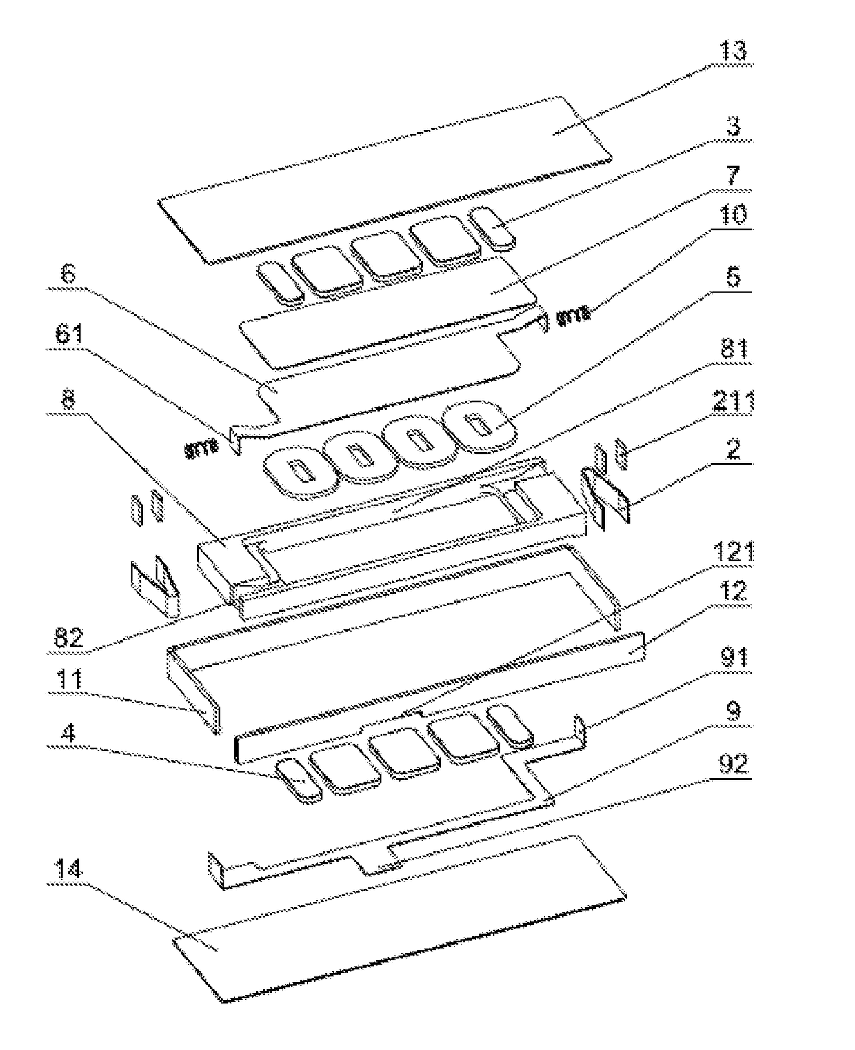
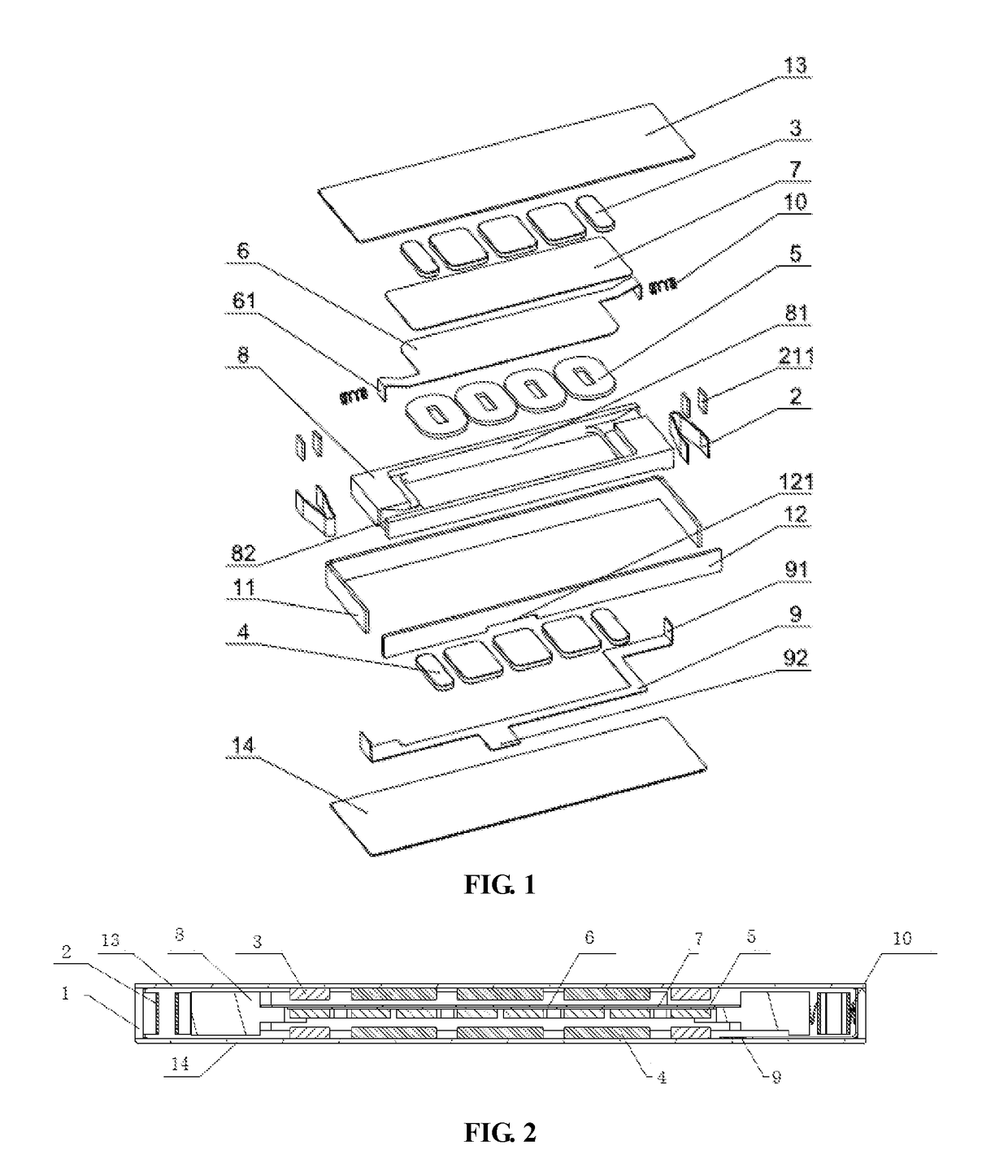
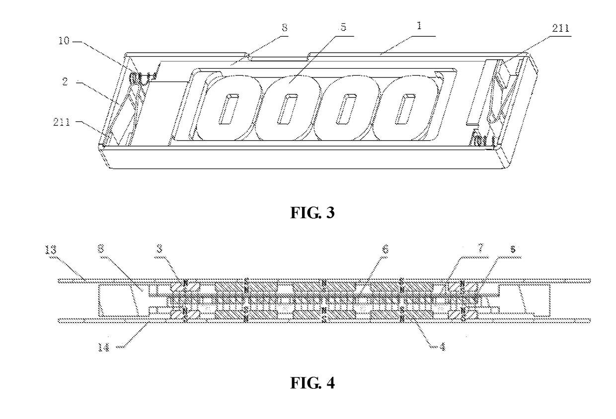
[0042]A linear motor, comprises a housing 1 having an accommodation space; a mass block 8 suspended in the accommodation space of the housing 1 by an elastic member 2; a coil 5 fastened on the mass block 8; and a magnet component comprising a first magnet and a second magnet that have opposite magnetic poles and are symmetrically disposed at an upper side and at a lower side relative to the coil 5 in the middle and positioned parallel to the centric plane of the coil 5. When the coil 5 is energized, the electromagnetic interaction between the coil 5 and the magnet component generates an electromagnetic force to drive the mass block 8 with the coil 5 to vibrate back and forth in a substantially horizontal direction.

[0043]In the above-mentioned linear motor, the design route that utilizes the motion of the coil 5 to drive the motion of the mass block 8, is different from the traditional route that utilizes magnet motion to drive mass block motion. As shown in FIG. 1 or FIG...


PUM


Abstract

The present invention provides a linear motor, wherein, a coil is fastened on a mass block that is suspended inside a housing, a first magnet and a second magnet that have opposite magnetic poles are symmetrically disposed at an upper side and at a lower side relative to the coil in the middle and positioned parallel to the centric plane of the coil, by arranging an upper magnetic steel and a lower magnetic steel at an upper side and at a lower side relative to the mass block in the middle and parallel to the mass block. In the linear motor of the present invention, the design route that utilizes coil motion to drive mass block motion is different from the traditional route that utilizes magnet motion to drive mass block motion. When the coil moves to either of the two lateral sides of the housing, both the first magnet and the second magnet simultaneously generate forces along a vertical direction of the housing, and as the first magnet and the second magnet having opposite magnetic poles are symmetrically disposed on both sides of the coil, the electromagnetic forces generated by the two magnets are equal in magnitude and opposite in direction, thus being counterbalanced with each other in the vertical direction, so as to ensure that the coil only moves back and forth in a horizontal direction, without generating vibration in a vertical direction, therefore, no noise related to vertical vibration is caused.

Description

CROSS REFERENCE[0001]This application is based upon and claims priority to Chinese Patent Application No. 201610187267.5 filed on Mar. 29, 2016 and titled “A LINEAR MOTOR”, the entire content of which is incorporated herein by reference.TECHNICAL FIELD[0002]The present invention relates to a horizontal vibration micro motor, which pertains to the technical field of linear vibration motors.BACKGROUND TECHNOLOGY[0003]Portable consumer electronic products such as mobile phones, tablet computers and handheld game consoles are becoming more and more popular with consumers. These electronic products normally use vibration signal as feedback information, for example, mobile phones have incoming call reminder, and handheld game consoles have vibration feedback. The vibration feedback function has become the most important application of vibration motors in the field of consumer electronics.[0004]The structure of a linear vibration motor in prior art is as follows: a suspension component is ...

Claims


Application Information

Patent Timeline
IPC IPC(8): H02K33/02
CPCH02K33/02H02K33/18H02K3/52H02K5/225
Inventor JIN, SHAOPINGFANG, SHAOBINCHEN, SHI
Owner JINLONG MACHINERY & ELECTRONICS CO LTD
Why Eureka
Try Eureka