Broad band radome for microwave antenna

a microwave reflector and broad band radome technology, applied in the direction of antennas, radiating element housings, other domestic articles, etc., can solve the problems of composite materials being significantly stronger and/or more expensive to manufacture than required, and incurring significant repair/replacement costs

Active Publication Date: 2017-10-19
COMMSCOPE TECH LLC
View PDF3 Cites 11 Cited by
  • Summary
  • Abstract
  • Description
  • Claims
  • Application Information

AI Technical Summary

Problems solved by technology

Because reflector antennas are often mounted in remote locations, such as high atop radio towers, a radome failure may incur significant repair/replacement ex...

Method used


Image

  • Broad band radome for microwave antenna
  • Broad band radome for microwave antenna
  • Broad band radome for microwave antenna

Examples


Embodiment Construction

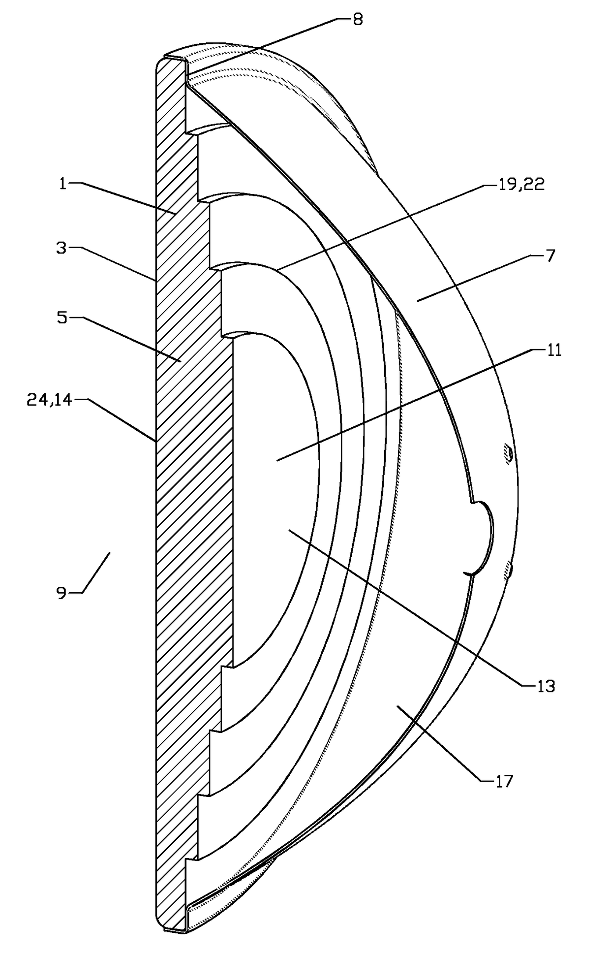
[0039]The inventors have recognized that a composite of a moisture resistant isotropic film outer layer and a structural layer of low density foamed polymer material can result in a radome with adequate strength which is essentially RF transparent, enabling a single radome to be utilized with a broad range of microwave frequency bands.

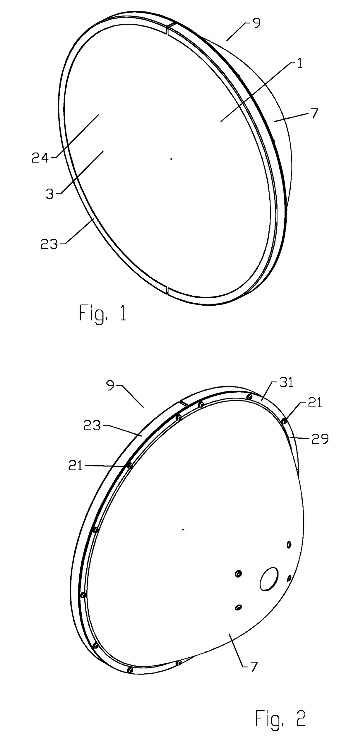
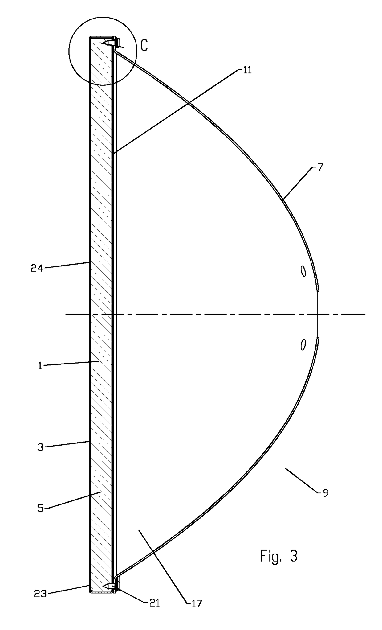
[0040]As shown for example in FIGS. 1-4, a radome 1 has an isotropic outer layer 3 coupled to a structural layer 5 of foam material that is retained on a reflector dish 7, a seating surface 8 of the radome 1 mating with a retaining flange at the distal end of the reflector dish 7, enclosing an open end of the reflector antenna 9. An isotropic material as applied herein is one in which the material has a substantially homogeneous distribution. That is, the material is not a woven or fiber infused material, but a substantially uniformly distributed homogeneous material, such as a polymer film, coating or the like. The outer layer 3 may be, for example, a...


PUM

PropertyMeasurementUnit
Diameteraaaaaaaaaa
Transmissionaaaaaaaaaa

Abstract

A radome for an antenna is provided as a composite of an isotropic outer layer and a structural layer of foamed polymer material. The composite is dimensioned to enclose an open end of the antenna. The radome may be retained upon the antenna by a retaining element and fasteners. The outer layer may be a polymer material with a water resistant characteristic. The structural layer may project inward and/or outward with respect to a plane of the seating surface of the radome.

Description

BACKGROUNDField of the Invention[0001]This invention relates to microwave reflector antennas. More particularly, the invention relates to a cost-efficient broad band radome for a microwave reflector antenna.Description of Related Art[0002]The open end of a reflector antenna is typically enclosed by a radome coupled to the distal end (the open end) of the reflector dish. The radome provides environmental protection and improves wind load characteristics of the antenna. Because reflector antennas are often mounted in remote locations, such as high atop radio towers, a radome failure may incur significant repair / replacement expense.[0003]A radome may be tuned to optimize the electrical performance of a reflector antenna, for example by dimensioning the radome surfaces to re-direct RF reflections in a desired direction. The radome materials and / or their thickness may be applied to self-cancel reflections. However, these tuned radomes then become antenna and / or operating frequency specif...

Claims


Application Information

Patent Timeline
IPC IPC(8): H01Q1/42H01Q15/16
CPCH01Q15/16H01Q1/424B29L2031/3456B29C44/1271B29K2105/04H01Q1/42B29K2101/12B29K2669/00B29K2023/06B29K2023/12B29K2025/06B29K2075/00H01Q1/005
Inventor RENILSON, IANCURRAN, JOHN S.WRIGHT, ALASTAIR D.LEWRY, MATTHEW ROBERTMACKAY, SHARONBAEV, SLAVI RUMENOV
Owner COMMSCOPE TECH LLC
Why Eureka
Try Eureka