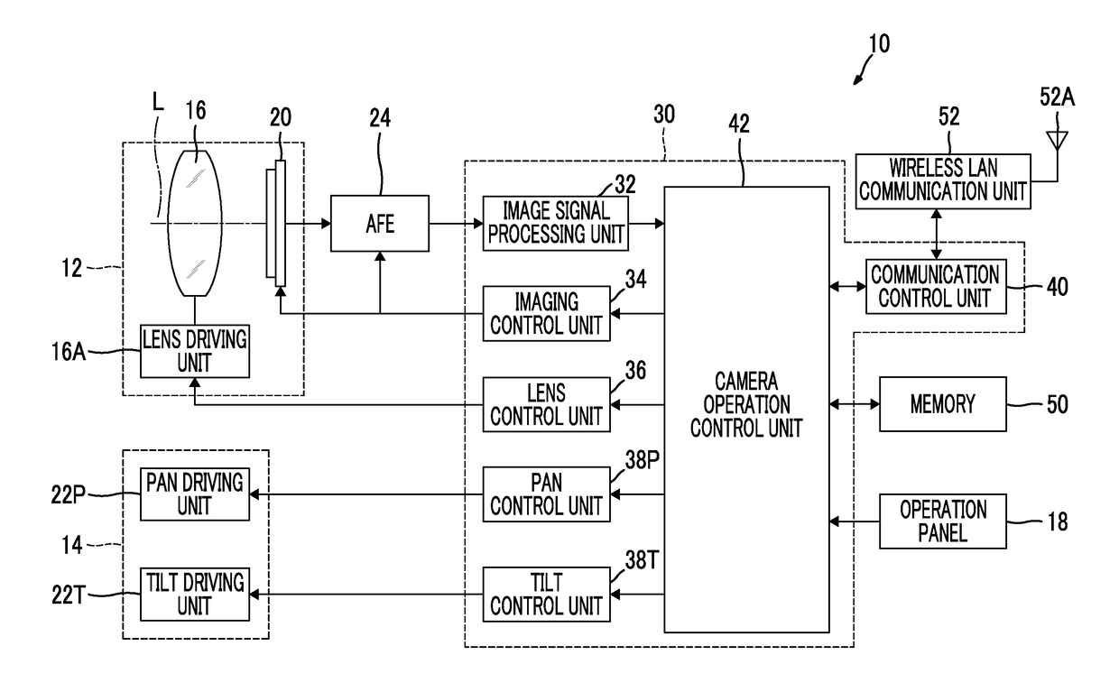
Tracking imaging control device, tracking imaging system, camera, terminal device, tracking imaging method, and tracking imaging program

Inactive Publication Date: 2017-12-07
FUJIFILM CORP
View PDF6 Cites 2 Cited by
  • Summary
  • Abstract
  • Description
  • Claims
  • Application Information

AI Technical Summary

Benefits of technology

The invention aims to provide a device, system, camera, terminal device, method, and program for tracking imaging that can easily detect and accurately track a target. The technical effects of this invention are improved efficiency, accuracy, and reliability in identifying and targeting specific individuals or objects.

Problems solved by technology

However, the method of JP2012-85090A has a disadvantage that a load of a process is large since it is necessary to detect the information on the subject that is a sequential target candidate.

Method used


Image

  • Tracking imaging control device, tracking imaging system, camera, terminal device, tracking imaging method, and tracking imaging program
  • Tracking imaging control device, tracking imaging system, camera, terminal device, tracking imaging method, and tracking imaging program
  • Tracking imaging control device, tracking imaging system, camera, terminal device, tracking imaging method, and tracking imaging program

Examples


modification example

Modification Example (1) of Tracking Control

[0150]Although a configuration in which the first target detection unit 220 and the second target detection unit 222 are selectively used on the basis of the target color ratio X is adopted in the above embodiment, a configuration in which results of the first target detection unit 220 and the second target detection unit 222 are selectively used on the basis of the target color ratio X can be adopted. That is, the position detection process itself is performed in both of the first target detection unit 220 and the second target detection unit 222, and whether or not to use which of the results is determined on the basis of the target color ratio X. In this case, a detection process of the position of the target in the first target detection unit 220 and a detection process of the position of the target in the second target detection unit 222 are performed in parallel.

Modification Example (2) of Tracking Control

[0151]Although the first tar...

modification example (

2) of Camera

[0182]Although the camera 10 of the above embodiment includes the function of the pan and tilt function, the camera may include at least the pan or tilt function. In the case of a camera including only a pan function, tracking of the target is performed only in a pan operation. Similarly, in the case of a camera including only a tilt function, tracking of the target is performed only in a tilt operation.

Modification Example of Target Setting Unit

[0183]In the above-described embodiment, the image captured by the camera 10 is displayed on the display 102 and a subject on the screen touched by the user is set as the target, but a method of setting the target is not limited thereto.

[0184]For example, a configuration in which a function of automatically detecting a face of a person from the image captured by the camera (a function of the face detection unit) is added as a function of the tracking imaging control device, and the face of the person detected using the function i...


PUM


Abstract

A tracking imaging control device includes a target color ratio calculation unit that calculates a ratio at which pixels with a certain range of hue occupy in the histogram as the target color ratio, with reference to the color of the target, and a tracking control unit that controls the pan and / or tilt operation of the camera to cause the camera to track the target, and the tracking control unit controls the pan and / or tilt operation of the camera on the basis of information on the position of the target detected by the first target detection unit when the target color ratio is equal to or lower than a threshold value, and controls the pan and / or tilt operation of the camera on the basis of information on the position of the target detected by the second target detection unit when the target color ratio exceeds the threshold value.

Description

CROSS-REFERENCE TO RELATED APPLICATIONS[0001]The present application is a Continuation of PCT International Application No. PCT / JP2015 / 083600 filed on Nov. 30, 2015 claiming priority under 35 U.S.C ยง119(a) to Japanese Patent Application No. 2015-029238 filed on Feb. 18, 2015. Each of the above applications is hereby expressly incorporated by reference, in their entirety, into the present application.BACKGROUND OF THE INVENTION1. Field of the Invention[0002]The present invention relates to a tracking imaging control device, a tracking imaging system, a camera, a terminal device, a tracking imaging method, and a tracking imaging program in which a pan and / or tilt operation of a camera including a pan and / or tilt function is controlled and imaging is performed while automatically tracking a target.2. Description of the Related Art[0003]Generally, in tracking imaging, a position of a target is detected from an image captured by a camera, and a pan and / or tilt operation of the camera is ...

Claims


Application Information

Patent Timeline
IPC IPC(8): H04N5/232G06T7/246G06T7/73G06T7/90G06V10/56
CPCH04N5/23296H04N5/23229H04N5/23219G06T7/246G06K9/00342G06T7/90G06T2207/20072G06T2207/20101G06K9/00228G06T7/73G06V40/161G06V40/23G06V10/56H04N23/66H04N23/61H04N23/611H04N23/635H04N23/69H04N23/695H04N23/10H04N23/80
InventorHAYASHI, DAISUKE
OwnerFUJIFILM CORP