

Smart case
- Summary
- Abstract
- Description
- Claims
- Application Information
AI Technical Summary
Benefits of technology
Problems solved by technology
Method used
Image

Examples
Embodiment Construction
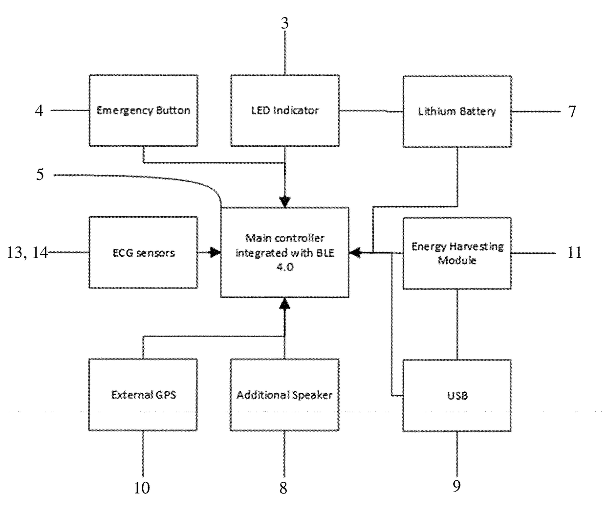
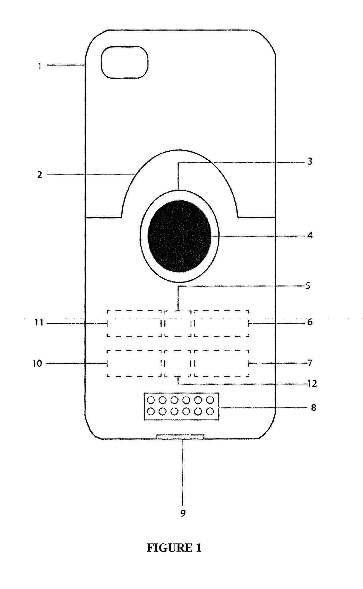
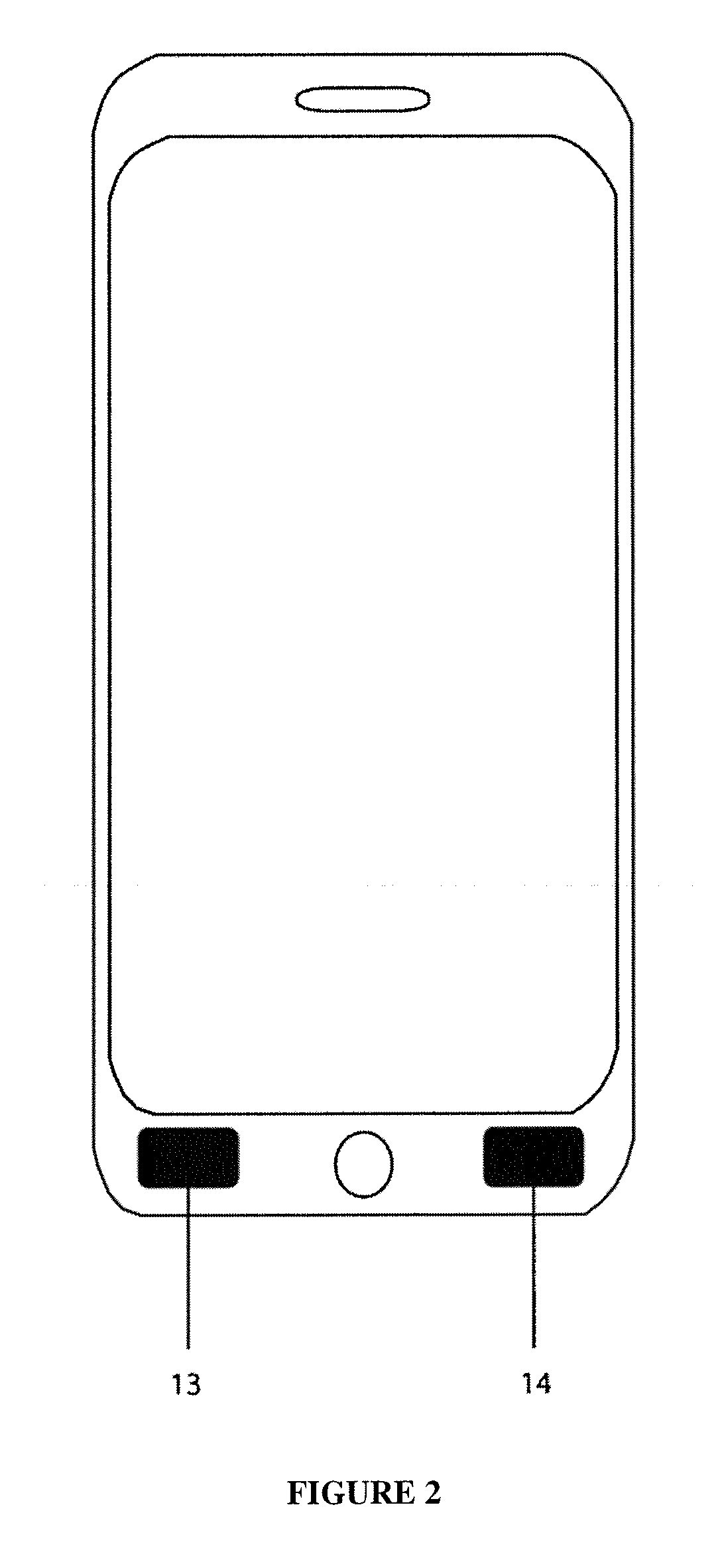
[0051]The present invention relates to a cell phone case, particularly to a multifunction back cover for a cell phone case, wherein the back cover has an rechargeable power source connected to a microcontroller and an emergency notification button used to trigger a variety of functional responses in cooperation with the application mode of the cell phone, wherein said microcontroller is in electronic communication with said emergency notification button.
[0052]Personal protection devices known in the art do not contemplate the herein disclosed novel features. One example is United States Patent Application Publication Number US 2016-0049982 A1 [1], describes a back cover for cell phone, particularly to a multifunction back cover for cell phone, wherein the back cover has an “entity” button providing at least one function, but which does not describe a microcontroller connected to the button, the circular LED or the electrodes described in the present invention.
[0053]Another example, ...
PUM
 Abstract
Description
Claims
Application Information