
Audio-signal correction apparatus, audio-signal correction method and audio-signal correction program

a technology of audio signal and correction method, applied in the direction of speech analysis, volume compression/expansion in digital/coded amplifiers, instruments, etc., can solve the problems of unreality of reproduced music, unnoticeable clipping, listeners may feel, etc., and achieve the effect of improving the clipped audio signal waveform

Active Publication Date: 2012-09-06
JVC KENWOOD CORP A CORP OF JAPAN
View PDF7 Cites 1 Cited by
  • Summary
  • Abstract
  • Description
  • Claims
  • Application Information

AI Technical Summary

Benefits of technology

[0009]A purpose of the present invention is to provide a an audio-signal correction apparatus, an audio-signal correction method and an audio-signal correction program for improving a clipped audio signal waveform.

Problems solved by technology

It is known that a mixing engineer uses a limiter in sound mixing to make clipping unnoticeable.
Therefore, listeners may feel that reproduced music is not realistic.

Method used


Image

  • Audio-signal correction apparatus, audio-signal correction method and audio-signal correction program
  • Audio-signal correction apparatus, audio-signal correction method and audio-signal correction program
  • Audio-signal correction apparatus, audio-signal correction method and audio-signal correction program

Examples


Embodiment Construction

[0023]Embodiments of an audio-signal correction apparatus, an audio-signal correction method, and an audio-signal correction program according the present invention will be explained with reference to the attached drawings. The same or analogous elements are given the same reference signs or numerals through the drawings with duplicated description thereof omitted.

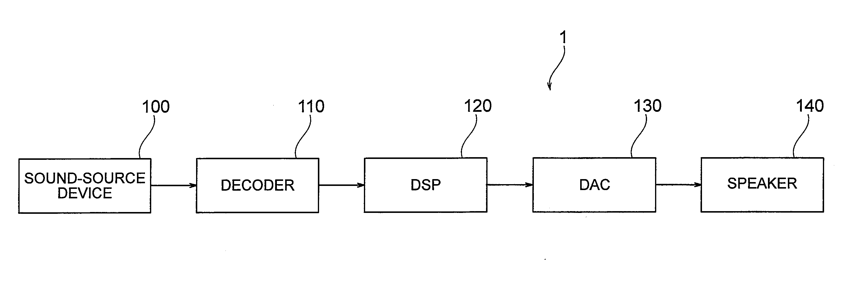
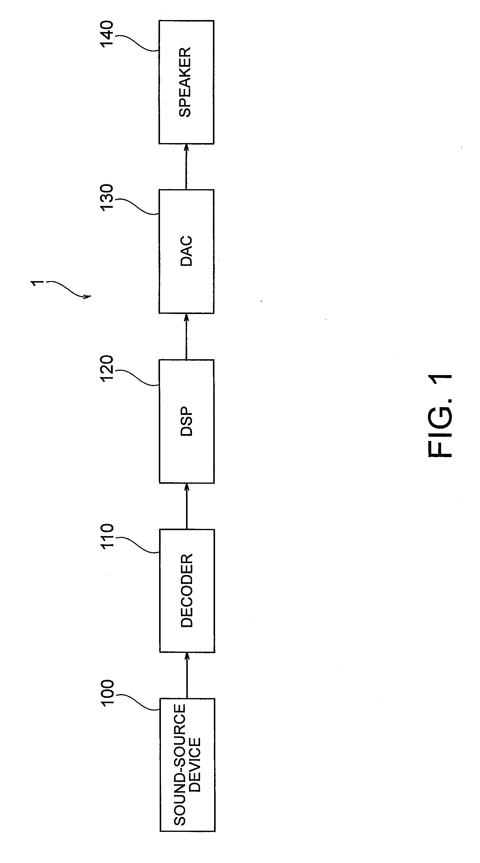
[0024]Described first with respect to FIG. 1 is an audio reproduction apparatus 1 having a clipped-waveform improving function (an audio-signal correction function).

[0025]The audio reproduction apparatus 1 is provided with a sound-source device 100, a decoder 110, a DSP (Digital Signal Processor) 120, a DAC (Digital-to-Analog Converter) 130, and a speaker 140.

[0026]The sound-source device 100 includes a CD player, a DVD player, etc. The sound-source device 100 outputs digital audio signals in the left (L) and right (R) channels, respectively. Each of a plurality of pieces of data that compose a digital audio signal has a v...


PUM


Abstract

Sequential digital audio signals are received to calculate a difference between each currently sampled digital audio signal and another digital audio signal sampled at one sampling period before each currently sampled digital audio signal. Differences for the sequential digital audio signals are stored. The number of digital audio signals consecutively clipped is counted in the received sequential digital audio signals. A specific difference is retrieved, from the stored differences, for a digital audio signal sampled at a specific number of sampling periods before each clipped digital audio signal. The specific number of sampling periods is determined based on the counted number of digital audio signals consecutively clipped. Each clipped digital audio signal is corrected based on the specific difference.

Description

CROSS-REFERENCE TO RELATED APPLICATIONS[0001]This application is based on and claims the benefit of priority from the prior Japanese Patent Application No. 2011-048382 filed on Mar. 4, 2011, the entire content of which is incorporated herein by reference.BACKGROUND OF THE INVENTION[0002]The present invention relates to an audio-signal correction apparatus, an audio-signal correction method and an audio-signal correction program for improving a clipped audio signal waveform.[0003]It is required for an audio reproduction apparatus to give listeners the feeling of being at a live performance and full impact of the live performance when reproducing music especially pop, which is achieved by raising the sound level of reproduced music, as already known.[0004]However, there is the maximum for the magnitude of reproducible sound level while music is being recorded in storage media such as CDs and DVDs. This is because, for storage media such as CDs and DVDs, it is required for music data t...

Claims


Application Information

Patent Timeline
Patent Type & Authority Applications(United States)
IPC IPC(8): G06F17/00G10L19/00G10L21/0332
CPCH03G3/002G10L21/0332H03G7/007H03G11/008G06F17/00
Inventor NAKAMURA, MASAMI
Owner JVC KENWOOD CORP A CORP OF JAPAN
Learn More