Wheel speed sensor driving mechanism

a technology of speed sensor and driving mechanism, which is applied in the direction of speed/acceleration/shock measurement, measurement device, instruments, etc., can solve the problems of anti-lock brake system operation error or abnormal indication of electronic tachometer, prior art designs are not practical for use with advanced electronic tachometers or computer-based abs (lock brake system control units), and achieves convenient mounting and dismounting. , the effect of reducing friction

Active Publication Date: 2018-04-05
SU KUO HSIN +1
View PDF0 Cites 0 Cited by
  • Summary
  • Abstract
  • Description
  • Claims
  • Application Information

AI Technical Summary

Benefits of technology

[0010]The present invention has been accomplished under the circumstances in view. It is one object of the present invention to provide a wheel speed sensor driving mechanism for motorcycle, which facilitates mounting and dismounting, reduces friction between the center hole of the follower unit and the central axle tube of the meter gear housing, and assures accurate component positioning and synchronous concentric rotation of the follower unit with the axle tube of the motorcycle front wheel hub to enhance accurate signal detection.

Problems solved by technology

The aforesaid two prior art wheel speed sensor driving mechanism designs are still not satisfactory in function and have drawbacks as follows:
2. The ABS (anti-lock brake system) or electronic tachometer signal reading error can occur, resulting in ABS (anti-lock brake system) operation error or electronic tachometer abnormal indication:
However, these prior art designs are not practical for use with an advanced electronic tachometer or computer-based ABS (anti-lock brake system) control unit.
The large recessed gaps 421′ for receiving the blocks 523′ at the driving ring 522′ can cause signal error or delay, leading to an erroneous tachometer indication or ABS (anti-lock brake system) false activation.
Further, due to friction between the center hole of the driving ring 522′ and the central axle tube 51″ of the housing 5″, the radial gap will become larger after long uses, and the error will be more obvious, leading to an ABS (anti-lock brake system) brake signal error.

Method used


Image

  • Wheel speed sensor driving mechanism
  • Wheel speed sensor driving mechanism
  • Wheel speed sensor driving mechanism

Examples


first embodiment

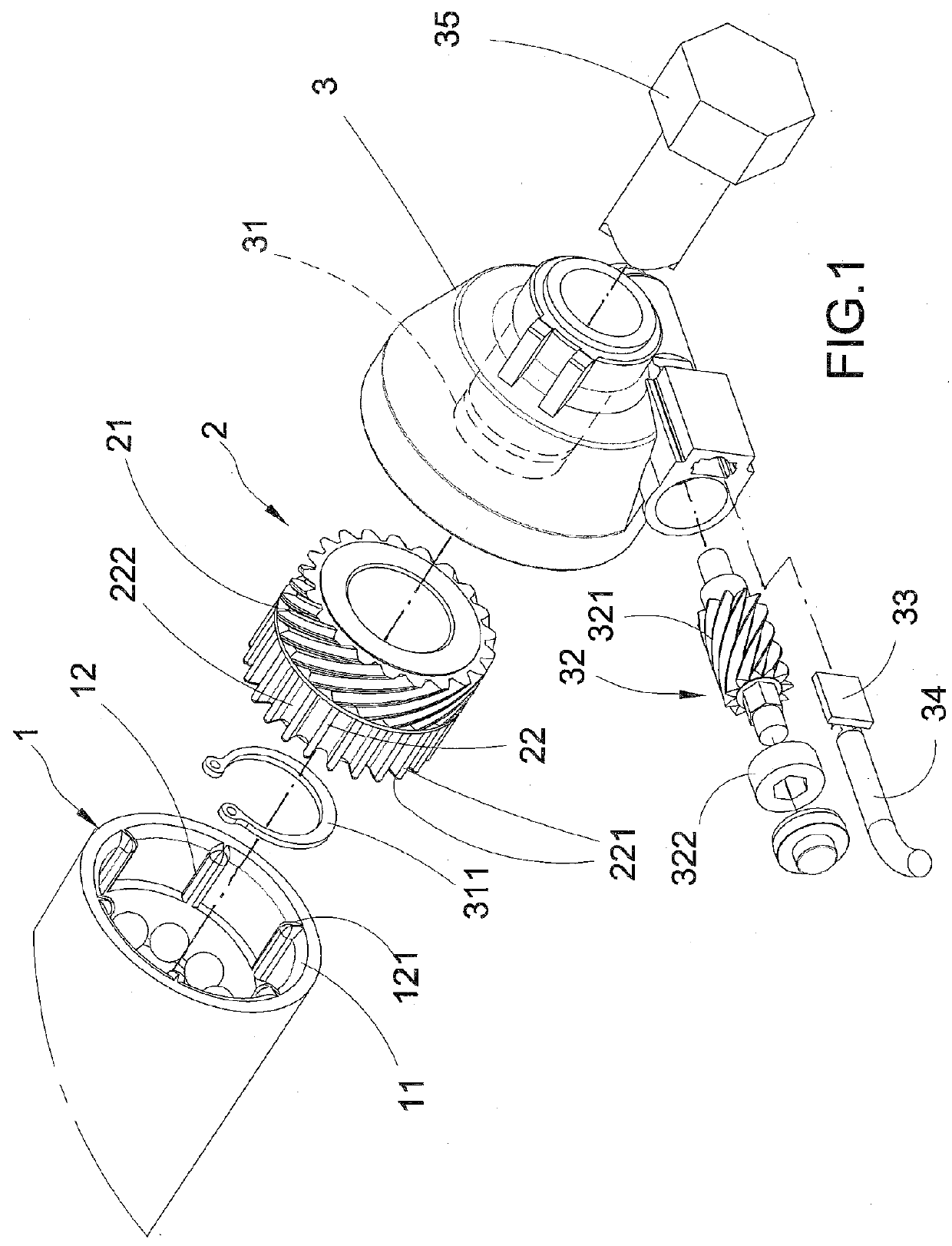
[0020]Referring to FIG. 1, a wheel speed sensor driving mechanism in accordance with the present invention is shown. The wheel speed sensor driving mechanism comprises a motorcycle front wheel hub axle tube 1, a follower unit 2, a meter gear housing 3 and a wheel speed sensing unit 32. The follower unit 2 is mounted on a central axle tube 31 of the meter gear housing 3, and secured thereto with a C-shaped retainer 311. The follower unit 2 comprises a gear means, for example, worm wheel 21, a plurality of ribs 22 equiangularly arranged around the periphery of one end of the worm wheel 21, and a mounting groove 222 defined between each two adjacent ribs 22. Each rib 22 of the follower unit 2 has a chamfered edge 221 at each of axial and radial ends thereof. The motorcycle front wheel hub axle tube 1 comprises a plurality of driving blocks 12 equiangularly spaced around an inner perimeter thereof. The number of the ribs 22 of the follower unit 2 is divisible by the number of the drivin...

second embodiment

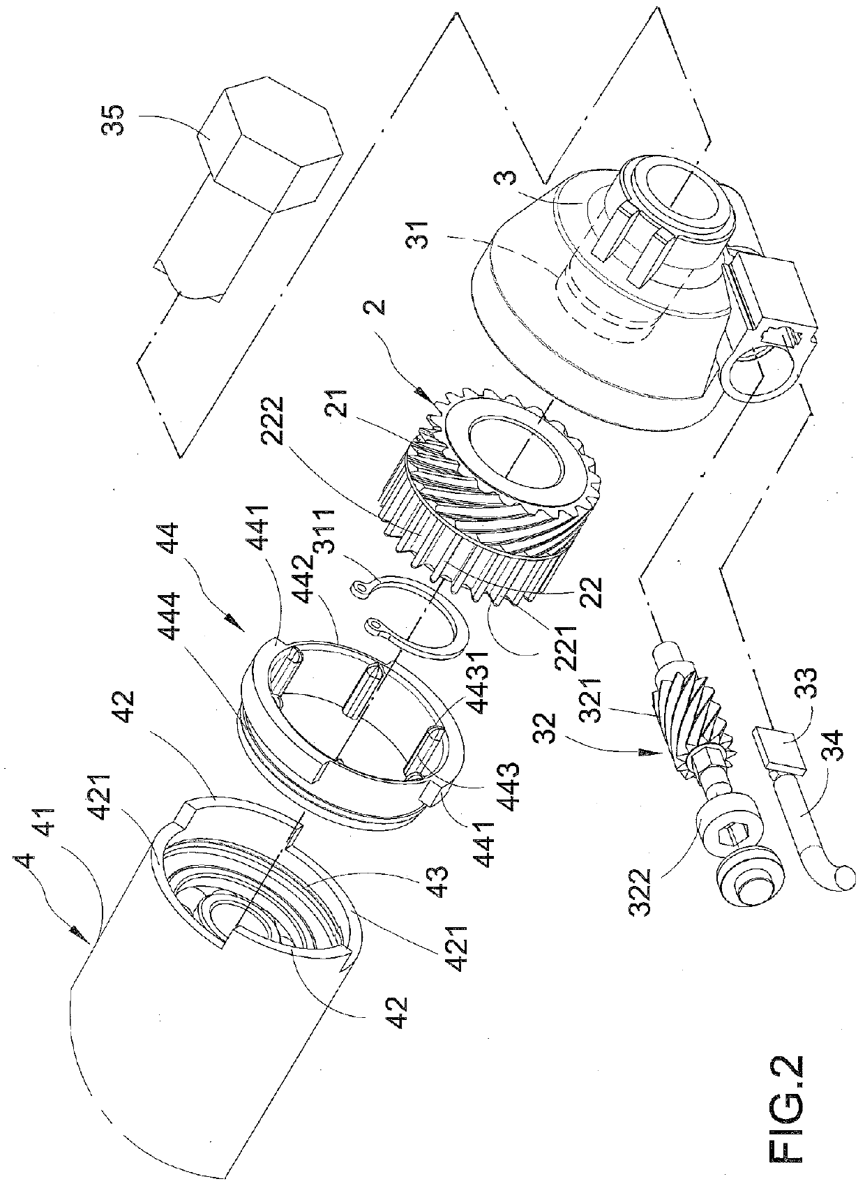
[0022]Referring to FIG. 2, a wheel speed sensor driving mechanism in accordance with the present invention is shown. As illustrated, the wheel speed sensor driving mechanism comprises an axle tube 41 of a conventional motorcycle front wheel hub 4, a driving member 44, a follower unit 2, a meter gear housing 3 and a wheel speed sensing unit 32. The follower unit 2 is mounted on a central axle tube 31 of the meter gear housing 3, and secured thereto with a C-shaped retainer 311. The follower unit 2 comprises a worm wheel 21, a plurality of ribs 22 equiangularly arranged around the periphery of one end of the worm wheel 21, and a mounting groove 222 defined between each two adjacent ribs 22. Each rib 22 of the follower unit 2 has a chamfered edge 221 at each of axial and radial ends thereof. The driving member 44 is mounted in a distal end of the axle tube 41 of the front wheel hub 4, comprising a chambered edge 442 at one end thereof, a plurality of driving blocks 443 equiangularly sp...


PUM


Abstract

A wheel speed sensor driving mechanism includes a motorcycle front wheel hub axle tube having chamfered driving blocks equiangularly spaced around an inner perimeter thereof, a follower unit concentrically mounted in the motorcycle front wheel hub axle tube and having chamfered ribs equiangularly arranged around the periphery of one end of the worm wheel and a mounting groove defined between each two adjacent ribs for receiving the chamfered driving blocks. Further, the number of the ribs of the follower unit is divisible by the number of the driving blocks of the motorcycle front wheel hub axle tube.

Description

BACKGROUND OF THE INVENTION1. Field of the Invention[0001]The present invention relates to motorcycle technology and more particularly, to a wheel speed sensor driving mechanism for motorcycle, which facilitates mounting and dismounting, reduces friction between the center hole of the follower unit and the central axle tube of the meter gear housing, and assures accurate component positioning and synchronous concentric rotation of the follower unit with the axle tube of the motorcycle front wheel hub to enhance accurate signal detection.2. Description of the Related Art[0002]FIG. 4 illustrates a wheel speed sensor driving mechanism for motorcycle according to the prior art. According to this design, the wheel speed sensor driving mechanism comprise a front wheel hub 4′ axle tube 41′ having two protruding lugs 42′ at a front end thereof and two opposing recessed gaps 421′ defined between the two opposing protruding lugs 42′ at two opposite sides, a meter gear housing 5′ with a centra...

Claims


Application Information

Patent Timeline
Patent Type & Authority Applications(United States)
IPC IPC(8): G01P1/08G01P3/42G01B7/14B60T8/171
CPCG01P1/08G01P3/42B60T2240/00B60T8/171B60T8/176G01B7/14
Inventor SU, KUO-HSINSU, TA-YU
Owner SU KUO HSIN
Why Eureka
Try Eureka