Tire pressure sensor device

a tire pressure sensor and sensor technology, applied in vehicle tyre testing, roads, instruments, etc., can solve the problems of complicated assembly procedure and high time consumption of the aforesaid prior art tire pressure sensor device, and achieve the effect of simple structure and convenient mounting and disassembly

Inactive Publication Date: 2014-12-30
CUB ELECPARTS
View PDF10 Cites 3 Cited by
  • Summary
  • Abstract
  • Description
  • Claims
  • Application Information

AI Technical Summary

Benefits of technology

[0006]The present invention has been accomplished under the circumstances in view. It is the main object of the present invention to provide a tire pressure sensor device, which has a simple structure and facilitates mounting and dismounting.

Problems solved by technology

Thus, the assembly procedure of the aforesaid prior art tire pressure sensor device is complicated and takes much time.

Method used


Image

  • Tire pressure sensor device
  • Tire pressure sensor device
  • Tire pressure sensor device

Examples


Embodiment Construction

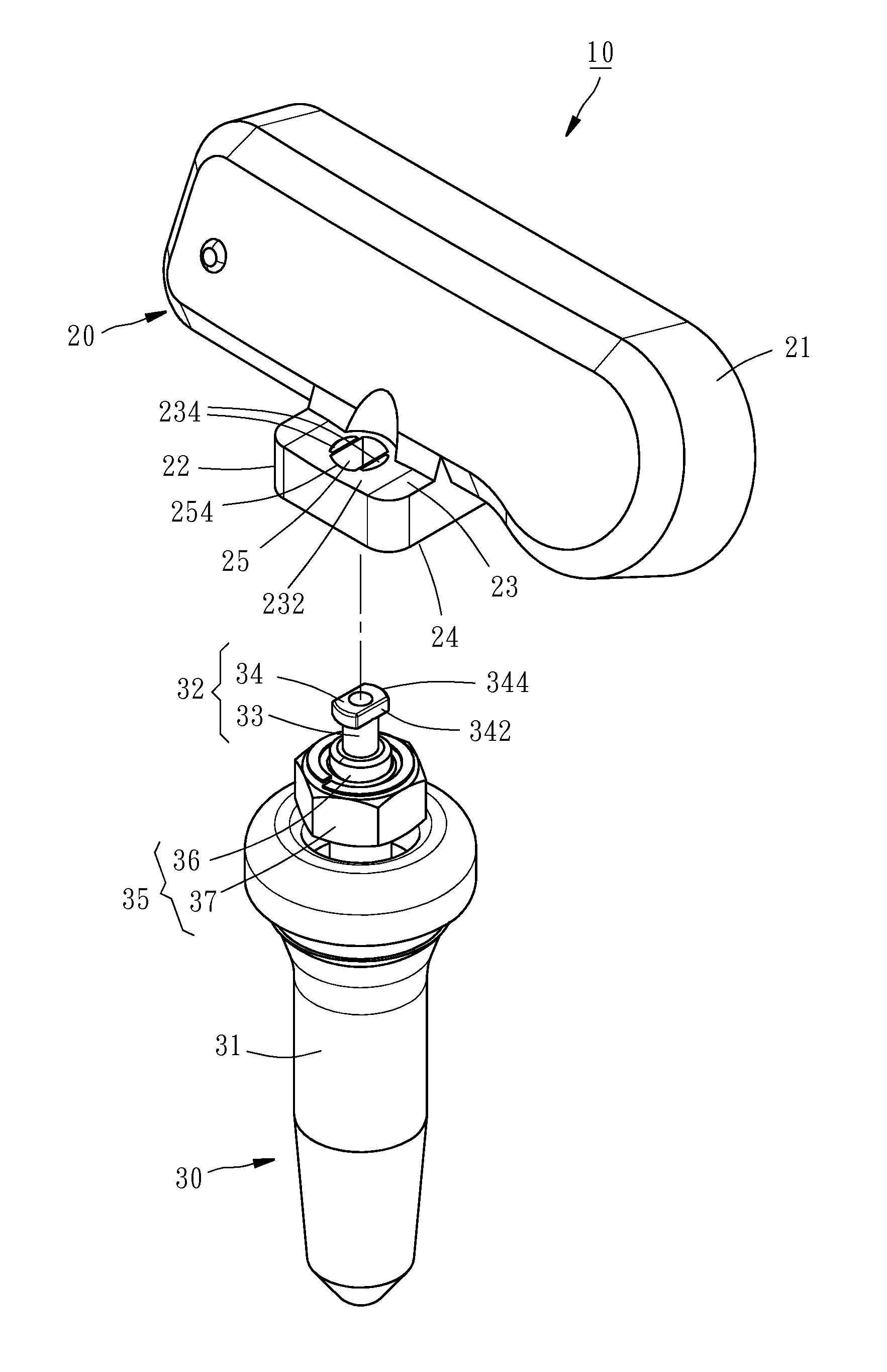
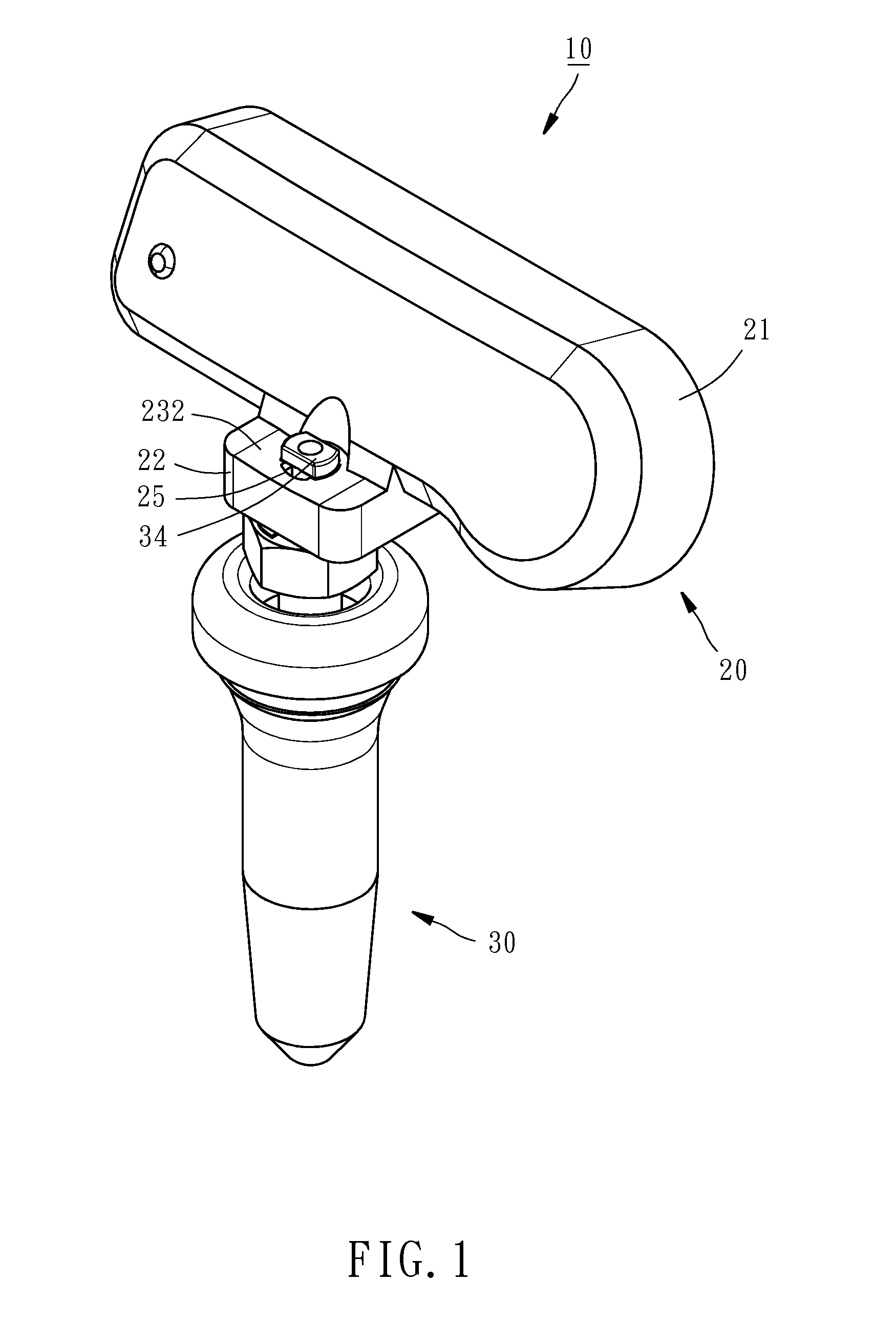
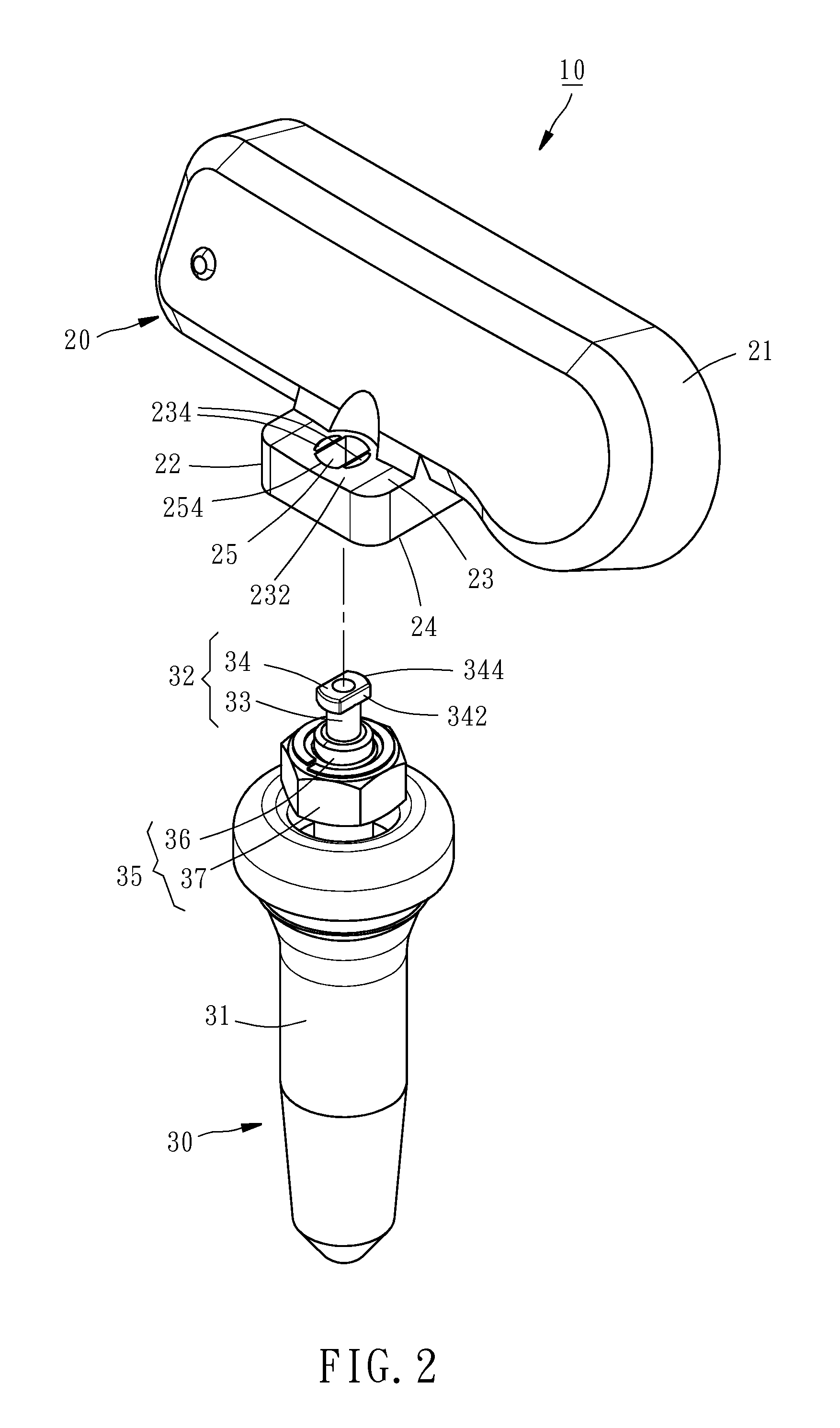
[0017]Referring to FIGS. 1 and 2, a tire pressure sensor device in accordance with the present invention is shown. The tire pressure sensor device 10 comprises a tire pressure sensor 20 and an air valve 30.

[0018]The tire pressure sensor 20 comprises a housing 21, a sensor component (not shown) accommodated in the housing 21 for sensing the pressure of a tire, and a mounting block 22 formed integral with a part of the housing 21. The mounting block 22 defines a first lateral side 23, a second lateral side 24 opposite to the first lateral side 23, and a through portion 25 between the first lateral side 23 and the second lateral side 24. Further, the first lateral side 23 defines thereon a coupling means that can be a recessed portion, protruding portion, or any other configuration located on the first lateral side 23. In this embodiment, the coupling means is a recessed portion 232 having a V-shaped cross section (see FIGS. 4 and 6). The through portion 25 has its one end terminating ...


PUM


Abstract

A tire pressure sensor device includes a tire pressure sensor including a housing and a mounting block defining a through portion in a coupling means thereof, and an air valve including an extension rod having a rod body rotatably inserted through the through portion and a stop block located at one end of the rod body and rotatable with the rod body between a first angular position where the stop block is kept in accurate alignment with the through portion and axially movable with the rod body through the through portion for allowing separation between the tire pressure sensor and the air valve and a second angular position where the stop block is stopped at the coupling means of the mounting block in a staggered manner relative to the through portion to prohibit separation between the tire pressure sensor and the air valve.

Description

BACKGROUND OF THE INVENTION[0001]1. Field of the Invention[0002]The present invention relates to tire pressure monitoring technology and more particularly, to a tire pressure sensor device, which facilitates installation.[0003]2. Description of the Related Art[0004]Because the air pressure of a vehicle tire s is of great concern to traffic safety, regular vehicles are commonly equipped with a tire pressure sensor device or monitoring system that provides real-time tire pressure information to the vehicle driver, avoiding traffic accidents.[0005]A conventional tire pressure sensor device is known comprising a tire pressure sensor and an air valve. During installation, a screw bolt is mounted in a through portion of the tire pressure sensor, and then a tool is operated to drive the screw bolt into a screw hole in the air valve, fastening the tire pressure sensor and the air valve together. During fastening up the screw bolt, the user must hold the air valve with one hand to avoid rota...

Claims


Application Information

Patent Timeline
Patent Type & Authority Patents(United States)
IPC IPC(8): B60C23/02B60C23/04G01M17/02
CPCB60C23/0493B60C23/0494
Inventor YU, SAN-CHUANWANG, TSAN-NUNGTSENG, SHIH-CHIEH
Owner CUB ELECPARTS
Why Eureka
Try Eureka