Assembly comprising a rim and a run-flat support

a technology of run-flat support and rim, which is applied in the direction of rims, tire beads, vehicle components, etc., can solve the problems of significant radial interference and achieve the effect of improving the ease of mounting

Inactive Publication Date: 2007-07-03
MICHELIN RECH & TECH SA
View PDF11 Cites 2 Cited by
  • Summary
  • Abstract
  • Description
  • Claims
  • Application Information

AI Technical Summary

Benefits of technology

[0010]During the mounting of the support, the support translates over the bearing surface of the rim. When the protuberance contacts the bearing surface, a significant radial interference exists. That portion of the base of the support containing the protuberance must deform radially to allow continued translation of the support to its final, mounted position. If the base of the support contains reinforcement elements in the immediate area of the protuberance, then this deformation will be restricted. Therefore, another advantage of the invention is to permit the localized deformation of the base of the support that, in turn, facilitates mounting and dismounting of the support on the rim.
[0011]In another version of the invention, both the base of the run-flat support and the bearing surface of the rim are each divided into at least two zones of different diameter connected by a transition zone. This geometry allows initially for a radial clearance or gap between the support and the bearing surface of the rim. However, when the support is in its final position, the desired interference fit exists in each of the zones. Thus, the desired pretension of the reinforcement elements is developed and ease of mounting is improved.
[0012]In this version of the assembly, the base portion of the support has an axial width LS and further comprises a first axial section laving a width L1 and a radially inner diameter D1 and a second axial section having a width L2 and a radially inner diameter D2 greater than the diameter D1, and a tapered transition section located between said first and second axial sections, and the bearing surface of the rim comprises a first axial section having a width L3 and a diameter D3 and a second axial section having a width L4 and a diameter D4 greater than the diameter D3, and a tapered transition section spaced between said first and second axial sections.
[0013]The desired interference fit is obtained when the diameter D3 of the rim is greater than the diameter D1 of the support, and / or when the diameter D4 of the rim is greater than the diameter D2 of the support.

Problems solved by technology

When the protuberance contacts the bearing surface, a significant radial interference exists.
However, when the support is in its final position, the desired interference fit exists in each of the zones.

Method used


Image

  • Assembly comprising a rim and a run-flat support
  • Assembly comprising a rim and a run-flat support
  • Assembly comprising a rim and a run-flat support

Examples


Embodiment Construction

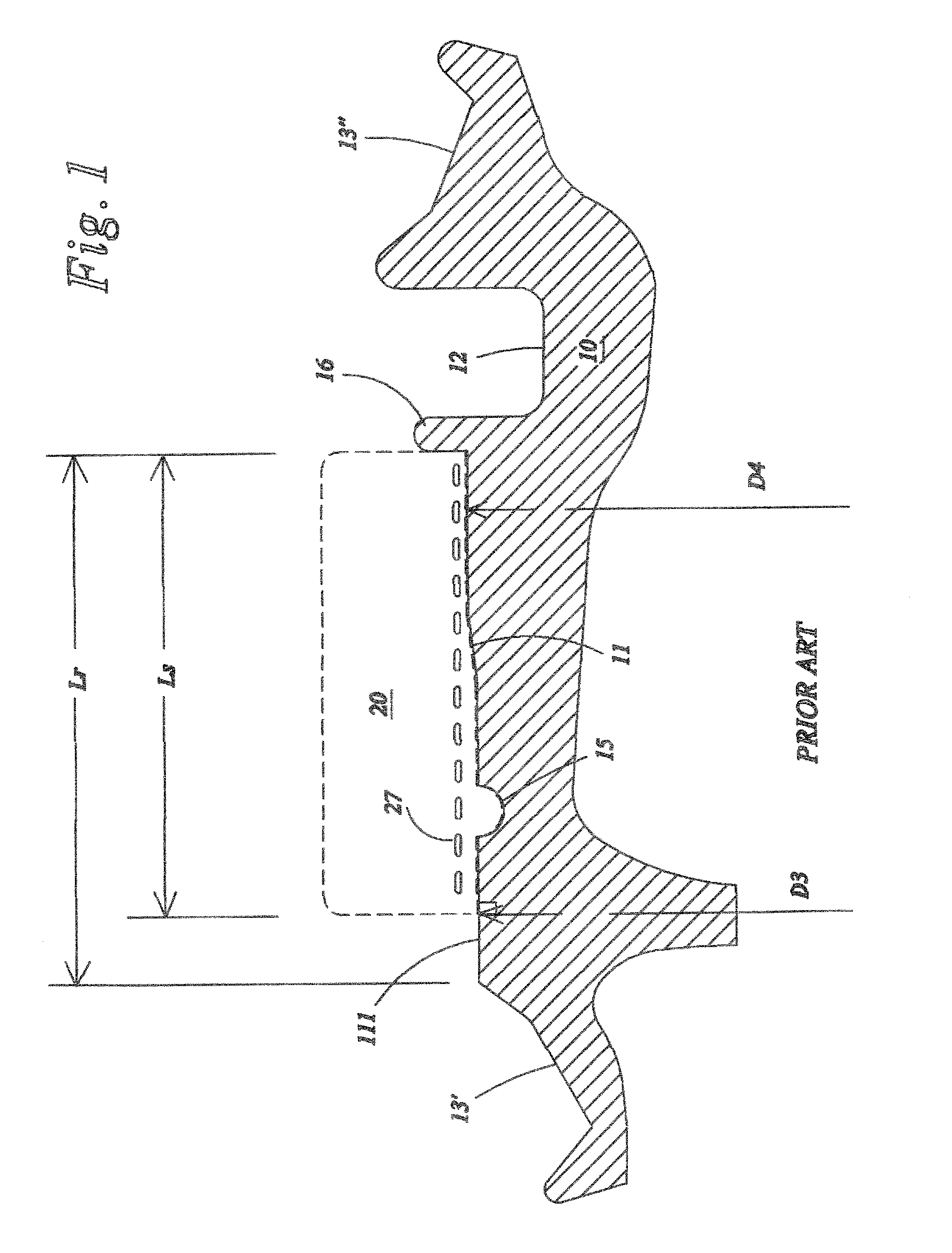
[0021]FIG. 1 depicts an assembly comprising a rim 10 and a run-flat support 20. The rim 10 has been adapted to accept a one-piece annular support 20. This necessitates a unique design for the tire, the rim, and the run-flat support. As shown, the rim 10 has two bead seats 13′, 13″ having unequal diameters. In particular, the diameter of the first bead seat 13′ is less than the diameter of the second seat 13″. The rim further comprises at least one mounting well 12 to facilitate mounting of the second bead of the tire on the rim 10 and a positioning stop 16 to limit the axial location of the run-flat support 20. The central portion 11 of the rim 10 serves as a bearing surface 111 to accept the run-flat support 20. As depicted in FIG. 1 the bearing surface 111 has a width Lr. The bearing surface further has a stepped shape to facilitate mounting of the support. That is to say, the bearing surface 111 has a first zone “I” of diameter D3 adjacent to the lesser diameter bead seat 13′, a ...


PUM


Abstract

An assembly comprising a rim having a substantially cylindrical bearing surface having at least one depression therein, and an annular run-flat support mounted on the bearing surface. The radially inner surface of the support further comprising a protuberance to engage the depression in the rim, and wherein a radially innermost base portion of the support includes a plurality of substantially circumferentially oriented reinforcement elements. The reinforcement elements are axially spaced apart, and the reinforcement elements are absent in an axial portion of the base portion radially outward of the protuberance.

Description

CROSS REFERENCE TO RELATED APPLICATIONS[0001]This application is a continuation of International Application No.: PCT / US03 / 19526, filed 20 Jun. 2003 and published 20 Jan. 2005 in English as International Publication No. WO 2005 / 005171 A1.BACKGROUND OF THE INVENTION[0002]The present invention relates to an assembly of a rim for mounting a tire and an annular run-flat support intended for mounting on the rim. This assembly is particularly useful for extending the distance a tire may travel at reduced or even zero air pressure. In particular, the present invention relates to a run-flat support having a particular arrangement of the reinforcement elements in the radially inner portion of the run-flat support. Many solutions have been proposed for providing an annular run-flat support fixed to a wheel rim to allow extending running after a partial or total loss of air pressure—capability for extended mobility. Many of these systems include multi-piece rims or multi-piece supports and the...

Claims


Application Information

Patent Timeline
Patent Type & Authority Patents(United States)
IPC IPC(8): B60C17/06B60B21/02B60C17/04
CPCB60B21/023B60B21/026B60B21/028B60B21/102B60B21/12B60C17/04B60C17/06B60B21/104B60C2017/068
Inventor CHRISTENBURY, DAMONZAWISZA, JEFFERY
Owner MICHELIN RECH & TECH SA
Why Eureka
Try Eureka