Safety Ring Support for Throwing Trap

a safety ring and support technology, applied in the direction of weapons, weapons, weapon components, etc., can solve the problems of high fabrication cost of the support arms, complicated dismount operation, increased processing cost and installation labor and time, etc., to facilitate storage of the safety ring support, facilitate mounting and dismounting, and save machining cost

Inactive Publication Date: 2017-06-22
LIU CHEH KANG
View PDF1 Cites 3 Cited by
  • Summary
  • Abstract
  • Description
  • Claims
  • Application Information

AI Technical Summary

Benefits of technology

[0009]The present invention has been accomplished under the circumstances in view. It is the main object of the present invention to provide a safety ring support for throwing trap, which facilitates mounting and dismounting without tools.
[0010]It is another object of the present invention to provide a safety ring support for throwing trap, which allows the user to dismount the support arms by hand without tools whenever desired, facilitating storage of the safety ring support.
[0011]It is still another object of the present invention to provide a safety ring support for throwing trap, which uses a rigid metal wire rod for making the support arms, saving machining cost.
[0012]It is still another object of the present invention to provide a safety ring support for throwing trap, which helps reduce the number of screw holes on the throwing trap main unit of the throwing trap, saving the cost.

Problems solved by technology

This dismounting operation is complicated.
Thus, the fabrication cost of the support arms 9 is high.3. It needs to make two screw holes 601 at each of the opposing left and right sides of the throwing trap main unit 60, increasing the processing cost and installation labor and time.

Method used


Image

  • Safety Ring Support for Throwing Trap
  • Safety Ring Support for Throwing Trap
  • Safety Ring Support for Throwing Trap

Examples


Embodiment Construction

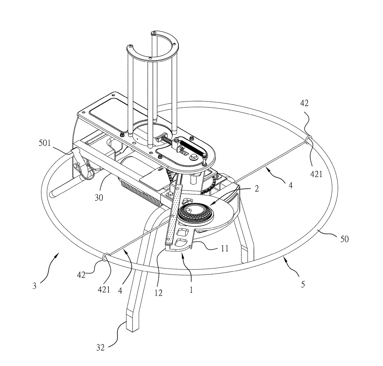
[0020]Referring to FIGS. 4-7, a safety ring support in accordance with the present invention is shown used in a throwing trap 3. The throwing trap 3 (see FIG. 7) comprises a throwing trap main unit 30 (see FIGS. 4-7) adapted for driving a throwing arm 1 to swing and to throw a clay 2 out of the holding target plate 11 thereof by means of centrifugal force subject to the operation of a push force plate 12 so that the user can aim at the flying clay 2 to perform a shooting training. Further, as illustrated in FIG. 7, the throwing trap 3 further comprises a front support 32. The safety ring support comprises two support arms 4 and a flexible tube member 50. The support arms 4 have respective one ends 41 thereof (see FIG. 4) respectively fastened to respective screw holes 301 at two opposite lateral sides of the throwing trap main unit 30 of the throwing trap 3 (see FIG. 4) near a front end of the throwing trap main unit 30, and respective opposite ends thereof respectively terminating ...


PUM


Abstract

A safety ring support for throwing trap is disclosed to include two support arms of rigid metal each having a threaded end piece at one end for thread-connected to a screw hole at one of two opposite lateral sides of the throwing trap main unit and a locating ring at an opposite end, and a flexible tube member having two opposite ends respectively inserted through the locating rings of the support arms and respectively connected to opposing connectors near a rear side of the throwing trap main unit. Thus, the safety ring support facilitates mounting and dismounting without tools.

Description

BACKGROUND OF THE INVENTION[0001]1. Field of the Invention[0002]The present invention relates to throwing trap technology and more particularly, to a safety ring support for throwing trap, which facilitates mounting and dismounting simply by hand without tools.[0003]2. Description of the Related Art[0004]A throwing trap main unit 60 of a throwing trap 6 generally comprises a drive shaft (not shown) having a connection rack, a throwing arm (not shown) fastened to the connection rack by fastening members 61. When the drive shaft is rotated, the throwing arm will be driven to swing, causing the clay to be thrown out of a holding target plate by means of centrifugal force. Thus, the user can shoot the flying clay, proceeding with shooting training. For safety's sake, the throwing trap main unit 60 is equipped with a safety ring support 8. For the mounting of the safety ring support 8, the throwing trap main unit 60 is configured to provide two pairs of screw holes 601 (see FIG. 1) at tw...

Claims


Application Information

Patent Timeline
Patent Type & Authority Applications(United States)
IPC IPC(8): F41J9/18
CPCF41J9/18F41A17/00
Inventor LIU, CHEH-KANG
Owner LIU CHEH KANG
Why Eureka
Try Eureka