Gyratory crusher main shaft and assembly

a technology of gyratory crusher and main shaft, which is applied in the direction of grain treatment, etc., can solve the problems of large wall thickness, difficult disassembly, and many problems with conventional protective sleeves

Active Publication Date: 2021-05-25
SANDVIK INTELLECTUAL PROPERTY AB
View PDF28 Cites 1 Cited by
  • Summary
  • Abstract
  • Description
  • Claims
  • Application Information

AI Technical Summary

Benefits of technology

[0006]It is an objective of the present invention to provide a gyratory crusher main shaft and a main shaft assembly (having a sleeve) that enables convenient mounting and dismounting of the protective sleeve at the upper end of the shaft that obviates a requirement for excessive heating of the main shaft and the use of grinding and cutting apparatus that otherwise carries a risk of damage to the main shaft and injury to service personnel.
[0007]It is a further specific objective of the present invention to provide a main shaft and sleeve assembly that facilitates mounting and dismounting of the sleeve at the shaft via control of a pressurised fluid delivered to the region of an axially upper end of the shaft radially between the shaft and the sleeve.
[0008]The objectives are achieved by providing a main shaft comprising at least one groove or channel indented on an outward facing external surface of the shaft. The groove is configured and dimensioned to receive a fluid under pressure to force separation of the sleeve from the main shaft. Providing the groove at the main shaft as opposed to the sleeve, is advantageous to maintain the strength and integrity of the sleeve to avoid fracture or splitting in response to the introduction of the pressurised fluid radially between the main shaft and the sleeve. The present invention is advantageous to allow the fluid to be introduced into the region between the main shaft and the sleeve via different routing options including in particular i) a conduit extending axially and / or radially at and / or within the main shaft and ii) a supply conduit extending through the sleeve wall. Reference to the conduit extending axially encompasses the conduit being aligned transverse or parallel to the longitudinal axis of the main shaft.

Problems solved by technology

However, a number of problems exist with conventional protective sleeves.
Additionally, disassembly is often problematic as the sleeve is required to be cut before it can be removed.
On large crushers, protective sleeves have a substantial wall thickness and this cutting operation can be time and labour intensive with the added risk of potential damage to the shaft.
Conventional mounting and dismounting procedures, due to the design of the main shaft and sleeve, are therefore disadvantageous in that they pose a risk of damage to the main shaft (and other components), injury to personnel and unacceptably long downtime of the crusher during repair and maintenance.

Method used


Image

  • Gyratory crusher main shaft and assembly
  • Gyratory crusher main shaft and assembly
  • Gyratory crusher main shaft and assembly

Examples


Embodiment Construction

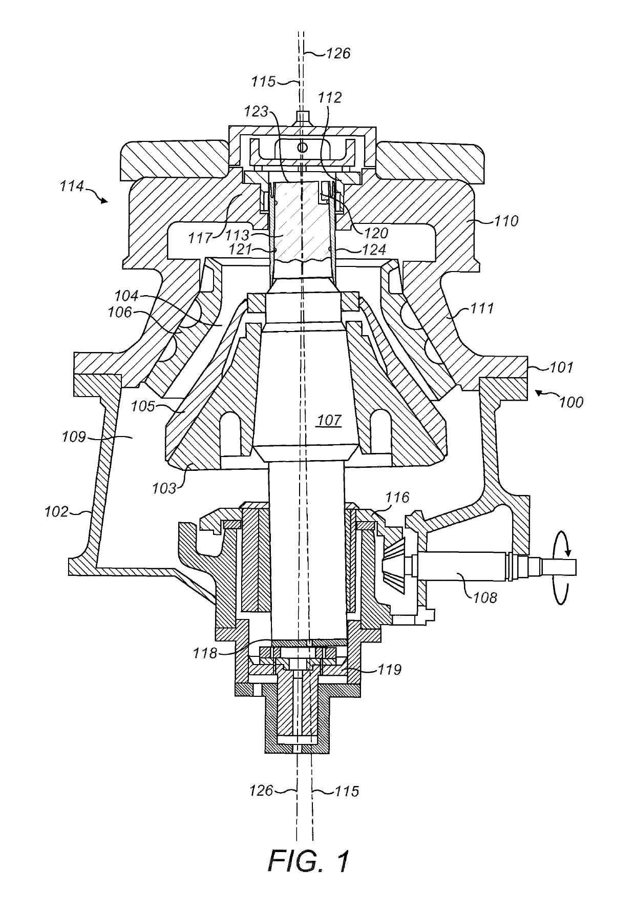
[0026]Referring to FIG. 1, a crusher comprises a frame 100 having an upper frame 101 and a lower frame 102. A crushing head 103 is mounted upon an elongate shaft 107 having a longitudinal axis 115. A first (inner) crushing shell 105 is fixably mounted on crushing head 103 and a second (outer) crushing shell 106 is fixably mounted at upper frame 101. A crushing zone 104 is formed between the opposed crushing shells 105, 106. A discharge zone 109 is positioned immediately below crushing zone 104 and is defined, in part, by lower frame 102.

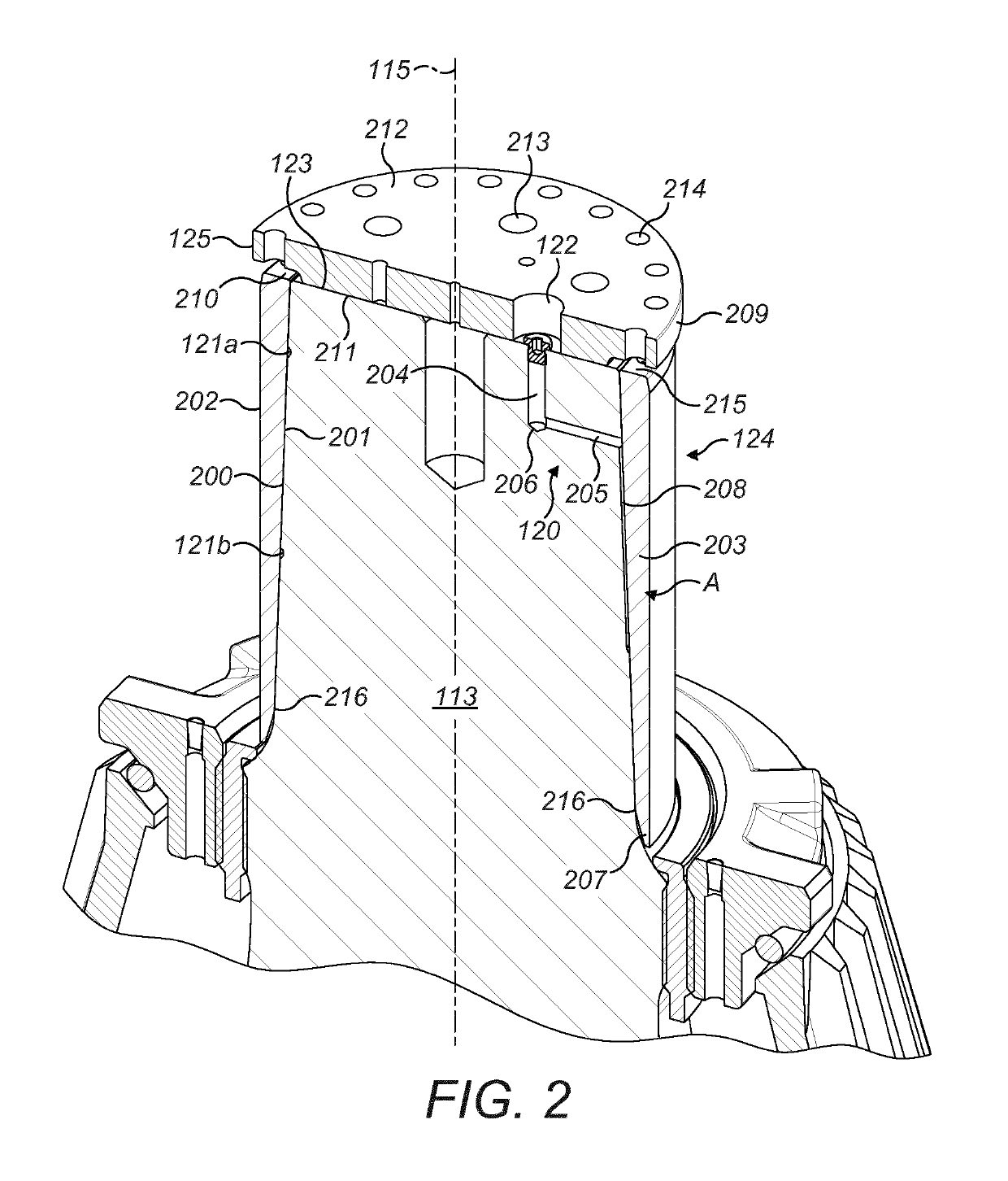
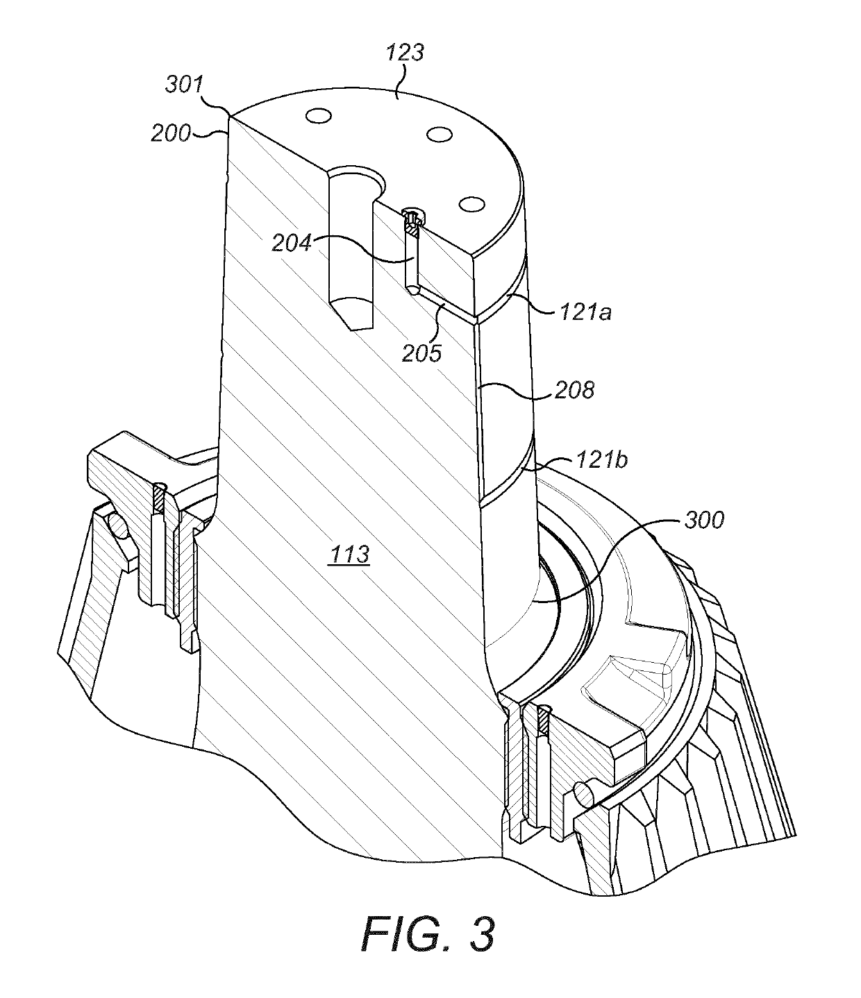
[0027]A drive (not shown) is coupled to main shaft 107 via a drive shaft 108 and suitable gearing 116 so as to rotate shaft 107 eccentrically about a longitudinal axis 126 of the crusher and to cause head 103 to perform a gyratory pendulum movement and crush material introduced into crushing chamber 104. A first (axial upper) end region 113 of shaft 107 is maintained in a rotatable position by a top-end bearing assembly 112 positioned intermediate be...


PUM


Abstract

A gyratory crusher main shaft assembly has a main shaft, an axially upper region of the main shaft including a tapered conical section with a protective sleeve friction fitted over the cone. To facilitate mounting and dismounting of the sleeve, at least one groove is indented within a radially external facing surface of the main shaft at the region of the cone to allow fluid to be introduced under pressure to the region between the sleeve and the cone.

Description

RELATED APPLICATION DATA[0001]This application is a § 371 National Stage Application of PCT International Application No. PCT / EP2014 / 060594 filed May 23, 2014 claiming priority of EP Application No. 13192402.9, filed Nov. 12, 2013.FIELD OF INVENTION[0002]The present invention relates to a gyratory crusher main shaft and main shaft assembly for positioning within a gyratory crusher and in particular, although not exclusively, to a main shaft having an axial upper end region that tapers radially inward and comprises at least one groove to receive a pressurised fluid to facilitate mounting and demounting of a sleeve at the shaft.BACKGROUND ART[0003]Gyratory crushers are used for crushing ore, mineral and rock material to smaller sizes. Typically, the crusher comprises a crushing head mounted upon an elongate main shaft. A first crushing shell is mounted on the crushing head and a second crushing shell is mounted on a frame such that the first and second crushing shells define together ...

Claims


Application Information

Patent Timeline
Patent Type & Authority Patents(United States)
IPC IPC(8): B02C2/00B02C2/06B02C2/04B02C2/02
CPCB02C2/06B02C2/02B02C2/04
Inventor BERGMAN, AXELLARSSON, MIKAEL MMALMQVIST, PATRICHALLBERG, ANDERSNILSSON, MATTS-AKEERIKSSON, FREDRIKERIKSSON, BENGT-ARNEHOLMBERG, ANNE
Owner SANDVIK INTELLECTUAL PROPERTY AB
Why Eureka
Try Eureka