Support bars and cycle carriers

Inactive Publication Date: 2017-03-09
C P WITTER
View PDF2 Cites 9 Cited by
  • Summary
  • Abstract
  • Description
  • Claims
  • Application Information

AI Technical Summary

Benefits of technology

[0005]The aim of our proposals is to provide new and useful lockable support bars, and cycle carriers using or incorporating them. Preferred embodiments o

Problems solved by technology

In a cycle carrier it is difficult to combine convenience with security against theft.
We note that these designs compromise or limit the spee

Method used


Image

  • Support bars and cycle carriers
  • Support bars and cycle carriers
  • Support bars and cycle carriers

Examples


Embodiment Construction

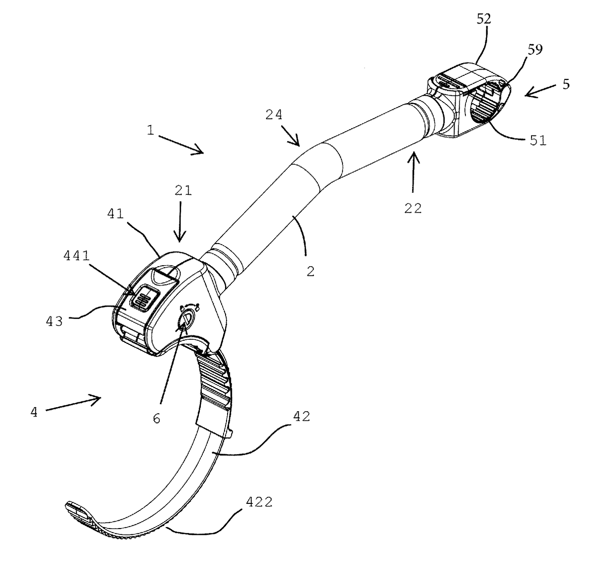
[0041]Embodiments of our proposals are now described by way of example, with reference to the accompanying drawings in which:

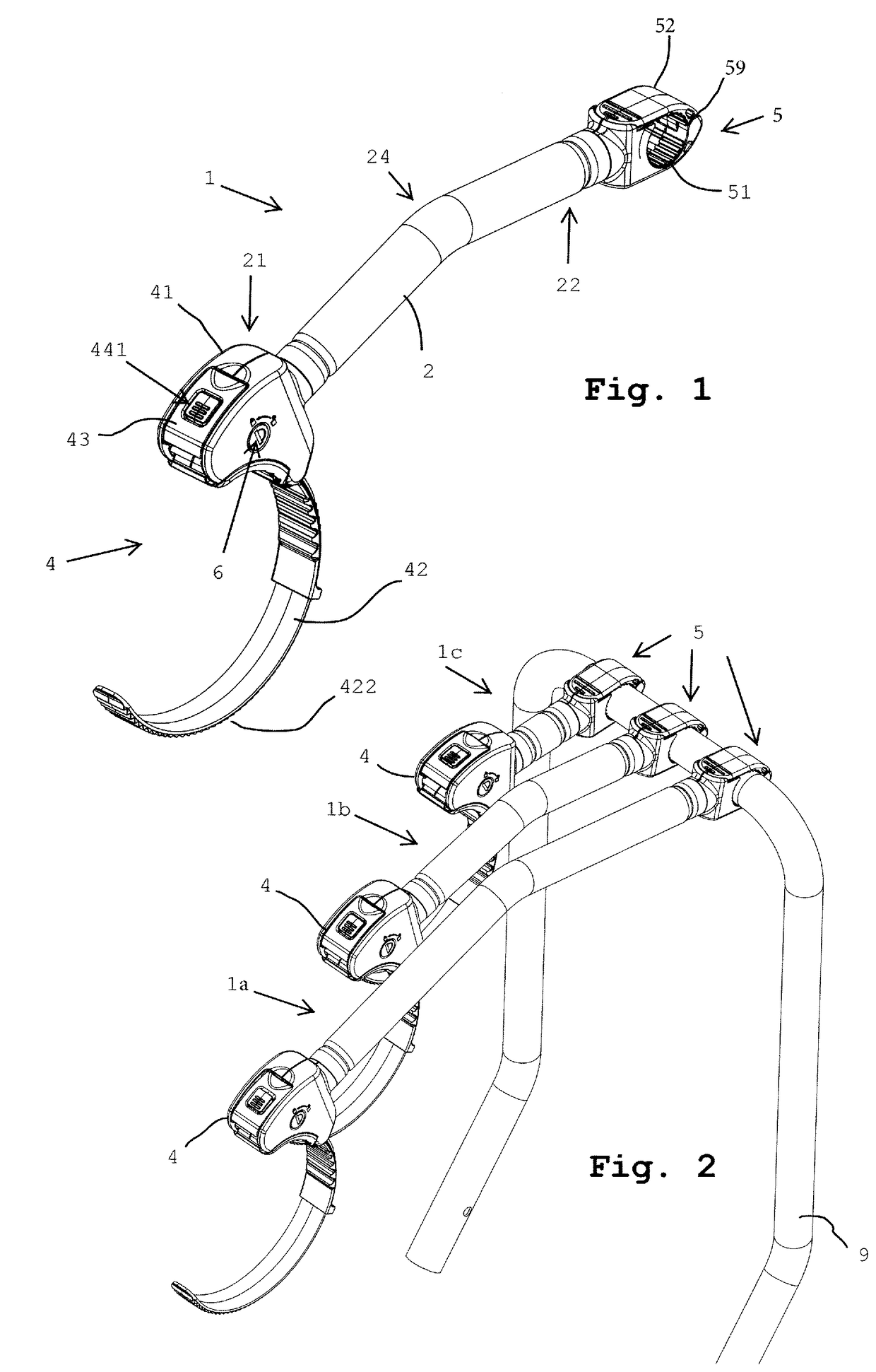
[0042]FIG. 1 is a general view of a support bar for a cycle carrier;

[0043]FIG. 2 shows a set of support bars mounted on a carrier frame (shown partially and schematically);

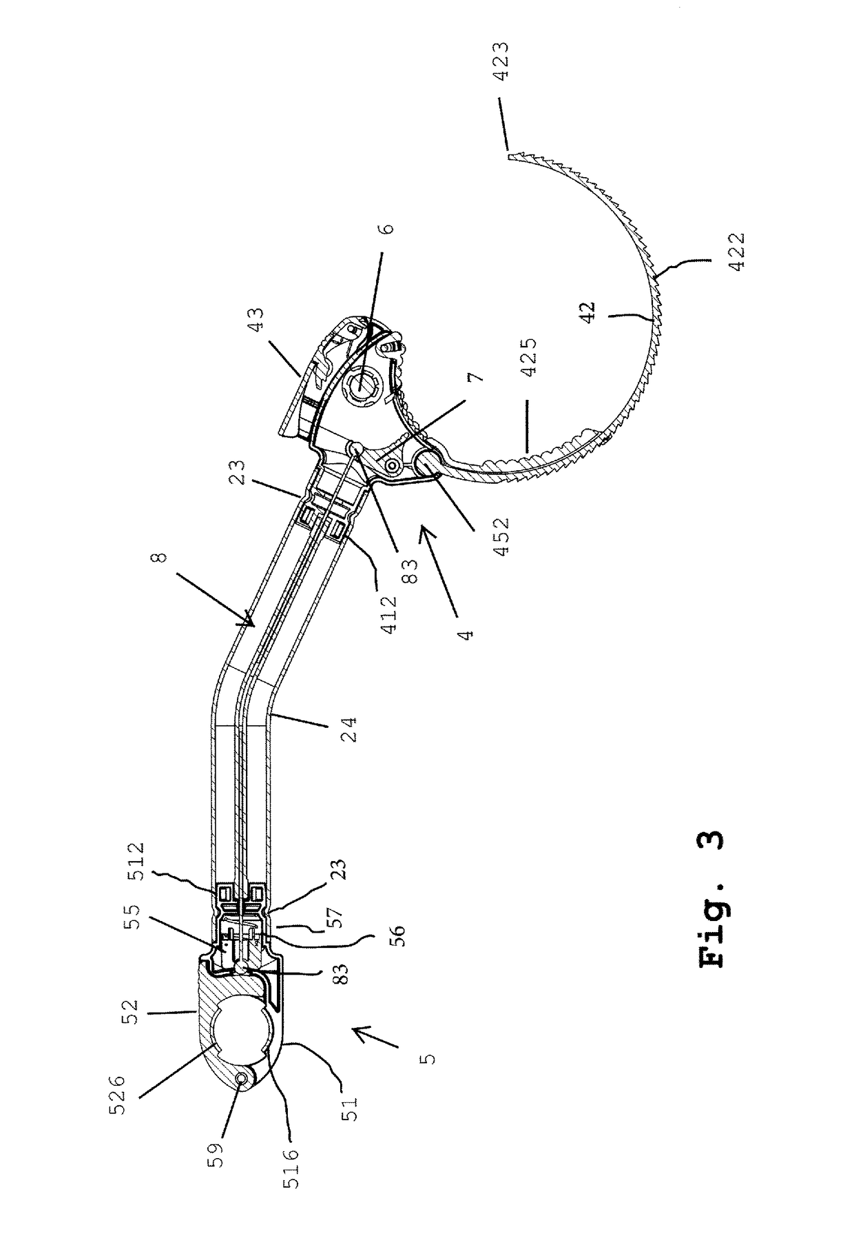
[0044]FIG. 3 is a vertical median section showing the general mechanism of a support bar;

[0045]FIG. 4 is a vertical median section of a first (cycle end) grip device, from one side;

[0046]FIG. 5 shows separately an actuator element housed in the first grip device;

[0047]FIG. 6 is a view onto a front contact face of the first grip device;

[0048]FIG. 7 shows separately a retainer element of the first grip device;

[0049]FIG. 8 is a vertical median section of the first grip device from the other side, showing a lock mechanism;

[0050]FIG. 9 is an oblique view from the bar side of a second (carrier end) grip device in an open position;

[0051]FIG. 10 is another oblique view of the open second grip device...


PUM


Abstract

A cycle carrier support bar has a cycle end grip device (4) at a first end of a tubular spacer bar (2) and a carrier end grip device (5) at the second end. The cycle end grip device can be a flexible strap (42) with a tensioning lever (43) and a key-operated lock (6). The carrier end grip device (5) can be a rigid clamp with opposed jaws (51,52) connected at a pivot (54) and closed releasably by a latch mechanism operated by a longitudinally-slidable carrier shuttle (55) carrying a detent of the latch. The latch is released to open the carrier end grip device (5) by pulling on the wire of a Bowden cable (8) which extends along the middle of the tubular spacer bar, and has an actuating lever (7) exposed through a window in the cycle end grip (4), so as to be accessible only when the cycle end grip (4) is open.

Description

FIELD OF THE INVENTION[0001]This invention has to do with support bars or retaining bars having grip devices, adapted for keeping objects held by the grip devices at a predetermined spacing from one another. We particularly propose support bars suitable for holding cycles in cycle carriers, and cycle carriers incorporating or including one or more of the support bars, although the concepts disclosed have broader uses.BACKGROUND[0002]It is known to carry bicycles on a vehicle using a cycle carrier, that is to say, a device which fixes (usually removably) to the vehicle and has a frame formed and adapted to support one or more bicycles stably. One known type, usually mounted at the rear of a vehicle using a towbar, has a frame including wheel supports on which the cycle wheels locate and rest, and a frame support portion, usually an upstanding frame portion, to which an upper part of the cycle frame is connected by a support bar to keep it upright.[0003]Carriers to carry two or more c...

Claims


Application Information

Patent Timeline
IPC IPC(8): B60R9/10F16B2/18F16B2/08
CPCB60R9/10F16B2/185F16B2/08
Inventor DICKINSON, MARTIN IAN
Owner C P WITTER
Why Eureka
Try Eureka