Touching screen device

A touch screen and receiving element technology, which is applied in the directions of instruments, calculations, electrical digital data processing, etc., and can solve the problems such as the decrease of detection accuracy of touch screen devices

Inactive Publication Date: 2004-04-21
FUJITSU LTD
View PDF0 Cites 43 Cited by
  • Summary
  • Abstract
  • Description
  • Claims
  • Application Information

AI Technical Summary

Problems solved by technology

Therefore, the region where the SAW propagating in the diagonal direction becomes weak (closer to the figure 2 The part of the diagonal line shown by the hatching in ) becomes wider, and the detection accuracy of the touch panel device may decrease

Method used


Image

  • Touching screen device
  • Touching screen device
  • Touching screen device

Examples


no. 1 example

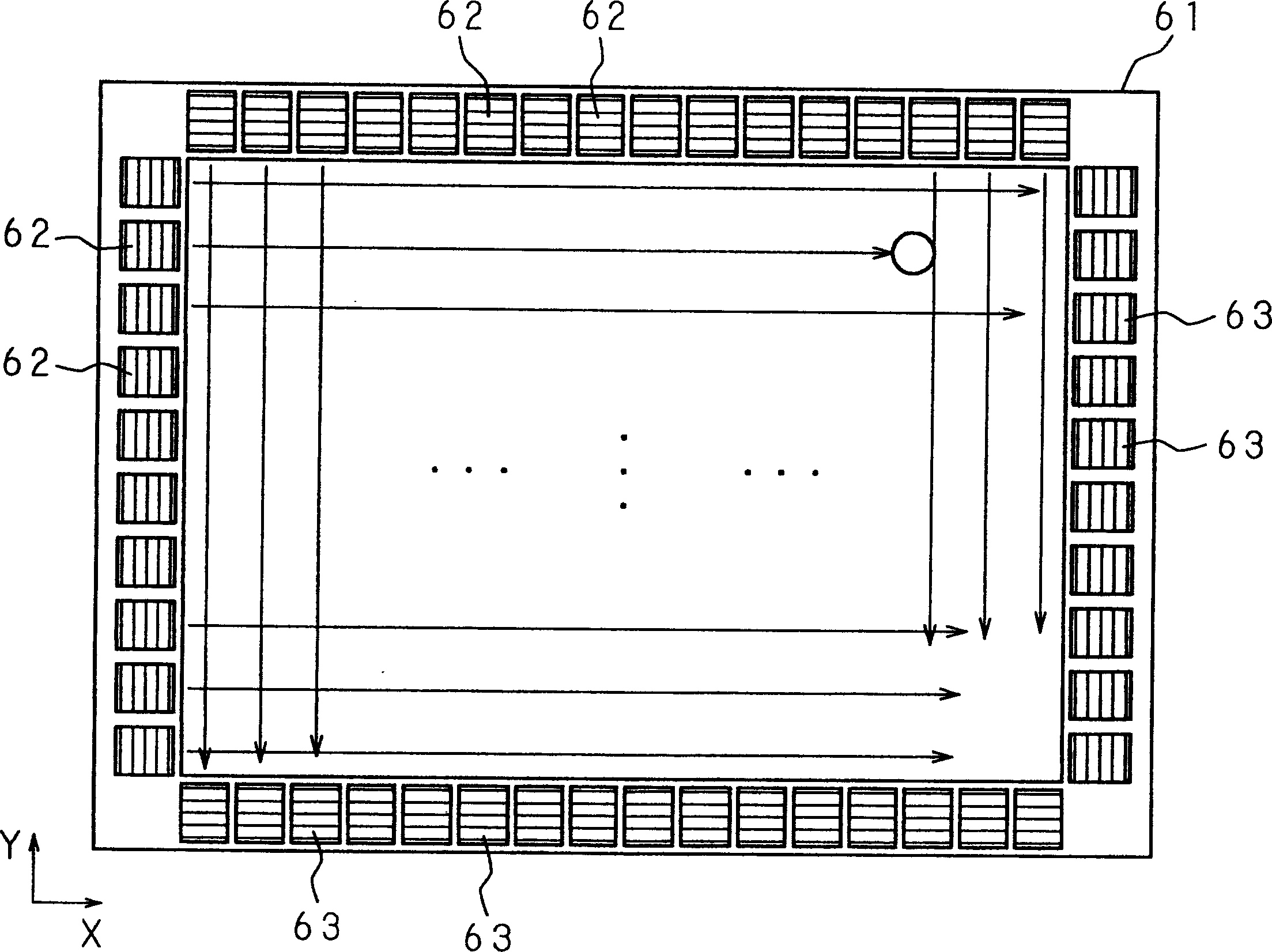
[0045] Figure 4 The structure of the touch panel device according to the first embodiment of the present invention is shown. exist Figure 4 In , reference numeral 1 denotes a rectangular non-piezoelectric substrate made of, for example, a glass material and a material capable of propagating surface acoustic waves, and a central portion surrounded by a dotted line is a detection region 1a capable of detecting a contact position.

[0046] In the frame area 1b outside the detection area 1a, that is, the peripheral portion of the non-piezoelectric substrate 1, the excitation element 2 for exciting the surface acoustic wave in two directions at the same time is provided on the upper side and the lower side of the frame area 1b, and on the left and right sides thereof The receiving element 3 that simultaneously receives surface acoustic waves from two directions is provided.

[0047] These excitation elements 2 and reception elements 3 have the same structure. Figure 5 is a pa...

no. 2 example

[0055] Figure 6 The structure of the touch panel device according to the second embodiment of the present invention is shown. exist Figure 6 in, with Figure 4 The same reference numerals denote the same or similar components.

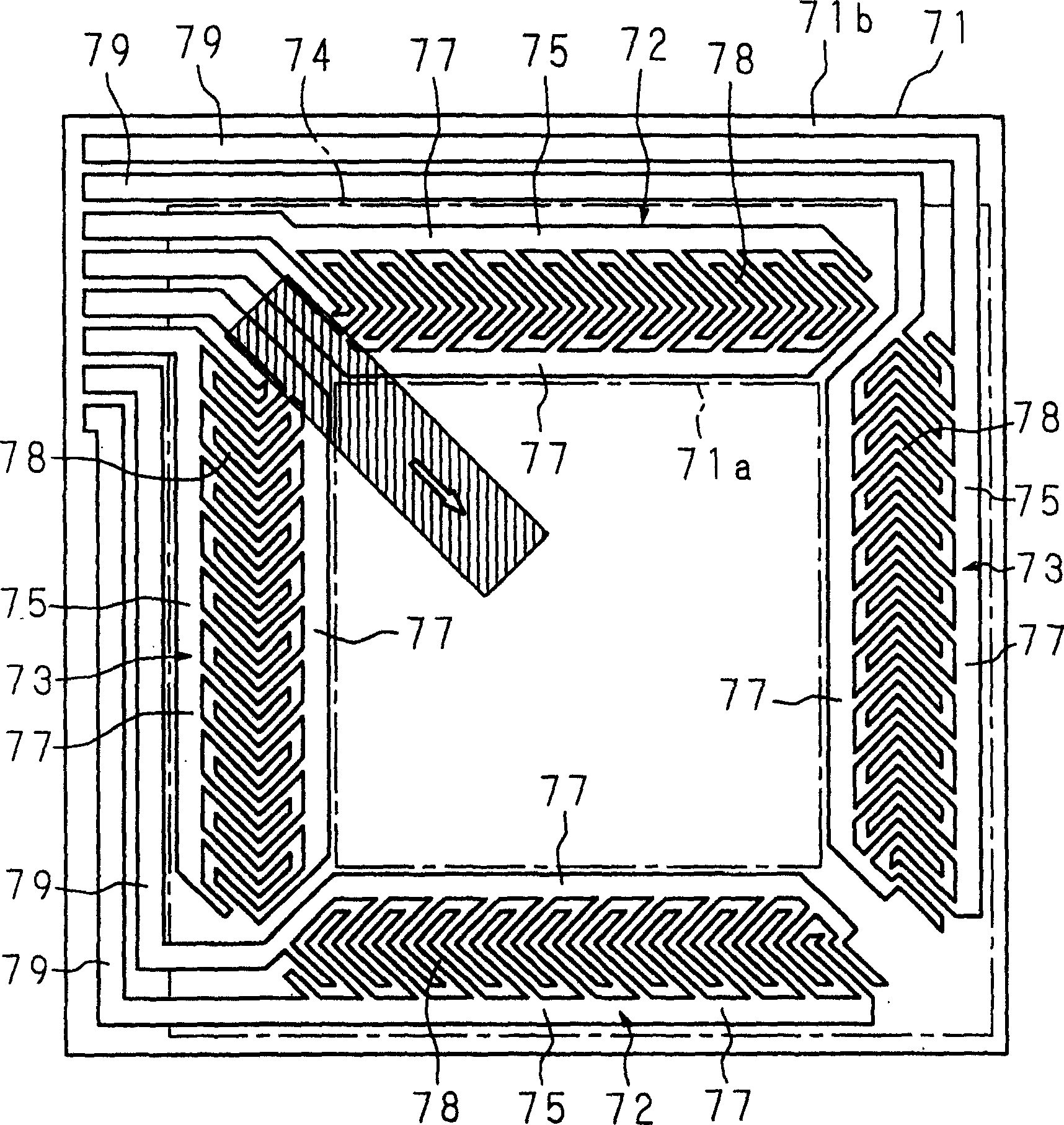
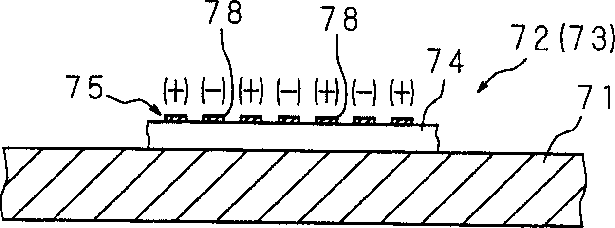
[0056] In the second embodiment, in order to reduce the resistance at the wiring portion, the conductive material 10 is overlapped on the peripheral lead 9 (by Figure 6 parts indicated by shading). More specifically, silver paste is coated on the previously formed peripheral leads 9 . Alternatively, the peripheral leads 9 may be directly formed by screen printing the conductive material 10 . Since other structures and operations are the same as those of the above-mentioned first embodiment, no further description is given here.

[0057] In the touch screen device, in order to connect each electrode of the excitation element 2 and the reception element 3 to an external circuit, a peripheral lead 9 must be drawn out from each comb electrode 5 an...

no. 3 example

[0059] Figure 7 is a partial structural diagram of a touch screen device according to a third embodiment of the present invention. exist Figure 7 in, with Figure 4 Components with the same reference numerals denote the same or similar components.

[0060] In the third embodiment, not only the electrode structure but also the peripheral leads 9 are separately provided on both surfaces of the piezoelectric body 4 . In other words, the peripheral leads 9 drawn out from the comb-shaped electrodes 5 and the peripheral leads 9 drawn out from the plate-shaped electrodes 6 are separately provided on the front and rear surfaces of the piezoelectric body 4 . exist Figure 7 In the example shown, the peripheral leads 9 (9a) drawn from the comb-shaped electrodes 5 (bus electrodes 7) of the upper side excitation element 2 are provided on one surface (front surface) of the piezoelectric body 4, and the element 2 is excited from the same upper side. On the other surface (rear surface...


PUM


Abstract

Each of excitation elements and receiving elements placed in a frame region of a non-piezoelectric substrate is constructed by forming a comb-like electrode on the front face of a piezoelectric body and forming a plate electrode (solid electrode) on the rear face thereof. The comb-like electrode is composed of a bus electrode and a plurality of V-shaped electrode fingers extended from the bus electrode. Drawn-round wires are provided to connect the comb-like electrode (bus electrode) and plate electrode to external circuits. Surface acoustic waves from the excitation elements located on the upper side and the lower side are simultaneously propagated in two directions respectively and the propagated surface acoustic waves are received by receiving elements located on the left side and the right side respectively.

Description

technical field [0001] The present invention relates to a touch screen device for detecting contact of an object such as a finger or a pen with the touch screen device, and more particularly to a touch screen device for detecting the contact position of an object by detecting the attenuation and cutoff of a surface acoustic wave (SAW) using an excitation element and a receiving element, Among them, electrodes are formed on the piezoelectric body to constitute the excitation element and the reception element. Background technique [0002] With the widespread use of computer systems, mainly personal computers, it has been adopted to input new information or provide various information to the computer system by clicking with an object such as a finger or a pen on the position of the display screen of the display device on which the information is displayed by the computer system. instruction device. In order to perform an input operation of information displayed on a display s...

Claims


Application Information

Patent Timeline
Patent Type & Authority Applications(China)
IPC IPC(8): G06F3/043G06F3/041
CPCG06F3/0436
Inventor 胜木隆史中沢文彦佐野聡高桥勇治
Owner FUJITSU LTD
Why Eureka
Try Eureka