Liquid crystal display device and method for manufacture of same

a liquid crystal display and display device technology, applied in the direction of thin material processing, instruments, chemistry apparatus and processes, etc., can solve the problems of reduced liquid crystal panel quality, poor viewing angle characteristics, and reduced yield, so as to improve the quality of liquid crystal panels and improve design freedom. , the effect of improving the quality of the liquid crystal panel

Active Publication Date: 2005-06-23
AU OPTRONICS CORP
View PDF5 Cites 42 Cited by
  • Summary
  • Abstract
  • Description
  • Claims
  • Application Information

AI Technical Summary

Benefits of technology

[0026] By means of this aspect of the invention, quality is improved and design freedom is enhanced.
[0027] Through this invention, a process to form an alignment control film prior to substrate bonding, by printing or other means, is rendered unnecessary. Hence numerous advantages are obtained, including improvement of the quality of liquid crystal panels, increases in yields, simplification of manufacturing facilities, streamlining of manufacturing processes, and lowering of costs.
[0028] Further, the desired alignment can easily be obtained even for thin, flexible film-shape substrates and for liquid crystal panels that is curved rather than flat, so that liquid crystal display devices with greater freedom of design can be realized.
[0029] Further, ultra-large motherglass for the substrates of liquid crystal panels can easily be accommodated.

Problems solved by technology

However, there is the problem that viewing-angle characteristics are poor when using the TN mode, and so various studies have been conducted in order to improve viewing-angle characteristics.
However, the MVA method requires that an alignment control film itself be installed; and such problems as reduced liquid crystal panel quality due to thickness irregularities when printing the alignment control film, lower yields due to inclusion of foreign matter, the complexity of equipment and processes, increased facility costs, increased material expenses, extended tact times, and other problems of cost increasing due to printing, cannot be avoided.
Further, although techniques are known (see for example Japanese Unexamined Patent Application Publication No. 11-95221 (scope of claims)) for the coexistence of cured resins and other polymers which regulate the liquid crystal alignment in the liquid crystal layer, incorporation of such techniques has not advanced to a level at which use of alignment control films has become unnecessary.
Further, while there has been rapid advance toward ultra-large motherglass for the substrates of liquid crystal panels, it is getting more and more difficult to provide equipment to print alignment control film that can accommodate such ultra-large motherglass.
Also, the use of equipment for printing alignment control films is limited to planar shapes, owing to the difficulty in handling film-shape substrates which are thin and flexible.

Method used


Image

  • Liquid crystal display device and method for manufacture of same
  • Liquid crystal display device and method for manufacture of same
  • Liquid crystal display device and method for manufacture of same

Examples


example 1

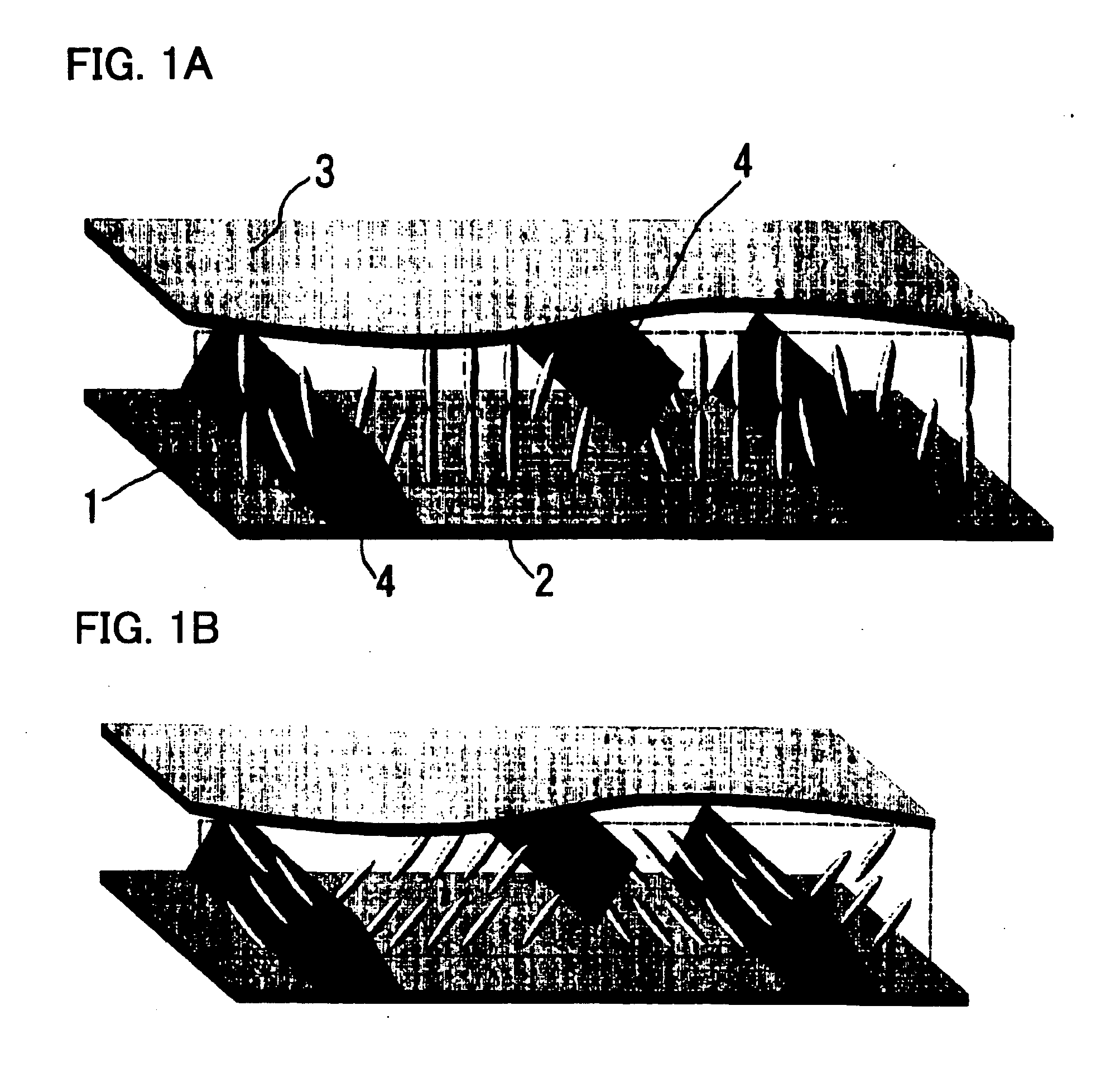
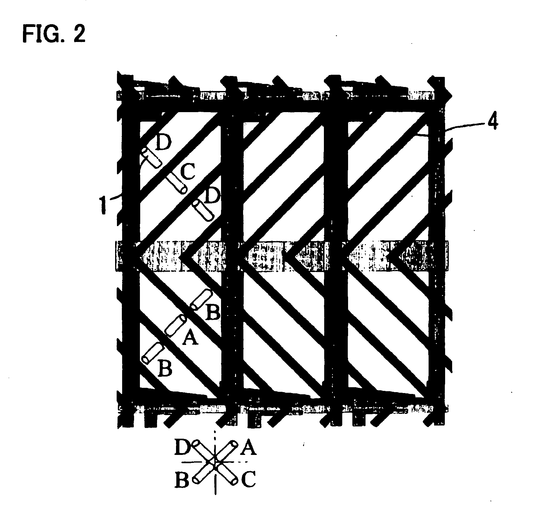
[0099] 1.3×10⁻⁴ mol / g lauryl acrylate was dissolved in liquid crystals A, produced by Merck and having a negative dielectric constant anisotropy; then, a monomer having two functional groups of this invention, having a ring structure as shown in (a) of FIG. 6 was dissolved in the amount of 1.3×10⁻⁵ mol / g, equivalent to one tenth of the above amount; this liquid crystal composition was injected into an evaluation cell and the cell was sealed. The liquid crystals A had the properties of being substantially vertically aligned when no voltage is applied, and being inclined with a voltage applied, in directions regulated by protrusions formed on the substrates or by slits in the electrodes.

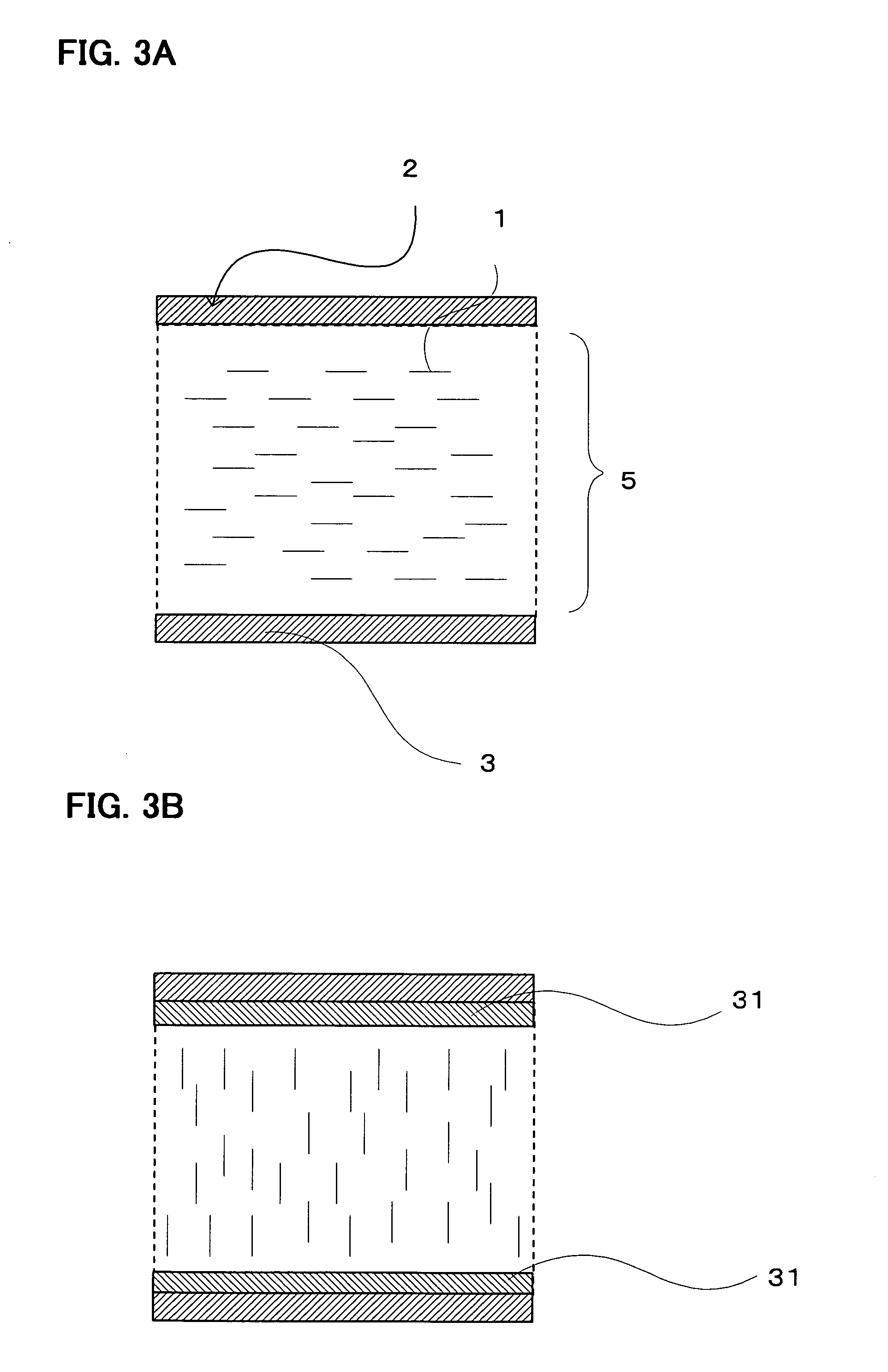
[0100] The evaluation cell with an MVA structure was fabricated using two glass substrates on which were formed electrodes of ITO (indium tin oxide), bonded together such that the cell thickness was 4.25 μm. No alignment control film was formed on the substrates.

[0101] (a) Alignment states were obser...

example 2

[0105] In (b) of Example 1, after irradiation at 1 mW / cm2 for 1500 mJ / cm2 (first process, equivalent to ultraviolet irradiation under the above first condition), the evaluation cell was heated to approximately 2° C. below the phase transition point for transitions from a liquid crystal state of the liquid crystal molecules to an isotropic state (N-I point). As a result, the white lines of alignment anomalies which had occurred up till then were nearly all eliminated. After this process, additional ultraviolet irradiation at 10 mW / cm2 for 7500 mJ / cm2 was performed (second process, equivalent to ultraviolet irradiation under the above second condition), and the aligned state was observed again. As a result, the small number of white lines that had remained before the additional irradiation vanished, and except for near the seal, substantially perfect vertical alignment was attained. Similarly to Example 1, white lines remained until the end near the seal, at which there is a particula...

example 3

[0107] After the irradiation at 1 mW / cm2 for 1500 mJ / cm2 in (b) of Example 1 (first process, equivalent to ultraviolet irradiation under the above first condition), instead of the heating performed in Example 2, the panel was passed through a laminator device for affixing a polarizing sheet, and pressure was applied. As a result, substantially the same effect as in the heating process performed in Example 2 was obtained. The results after an additional irradiation at an ultraviolet intensity of 10 mW / cm2 for 7500 mJ / cm2 (second process, equivalent to ultraviolet irradiation under the above second condition) were also substantially the same.


PUM

PropertyMeasurementUnit
dielectric constantaaaaaaaaaa
wavelengthaaaaaaaaaa
temperatureaaaaaaaaaa

Abstract

In a method for manufacture of a liquid crystal display device in which a liquid crystal composition is placed between two substrates, after which ultraviolet irradiation is performed to form a liquid crystal layer, a specific polymerizable compound is used, or specific ultraviolet irradiation conditions are adopted, or processing is comprised midway through the ultraviolet irradiation to activate the molecular motion of liquid crystal molecules or to deform the liquid crystal layer. A method for manufacture of a liquid crystal display device and a liquid crystal display device manufactured by this method are provided, in which an alignment control film is rendered unnecessary, and which has such advantages as improved quality of the liquid crystal panel, enhanced production yields, streamlined manufacturing facilities, simplified processes, and reduced costs.

Description

BACKGROUND OF THE INVENTION [0001] 1. Field of the Invention [0002] This invention relates to a liquid crystal display device and a method for manufacture of a liquid crystal display device. In particular, this invention relates to a liquid crystal display device which utilizes a state in which liquid crystal molecules are aligned vertically with no voltage applied, and to a method for manufacture of same. [0003] 2. Description of the Related Art [0004] In the prior art, as liquid crystal displays (LCDs) using an active matrix, TN-mode liquid crystal display devices in which liquid crystal material having a positive dielectric constant anisotropy is aligned parallel to the substrate surfaces, and with a 90° twist between the opposing substrates, have been widely employed. However, there is the problem that viewing-angle characteristics are poor when using the TN mode, and so various studies have been conducted in order to improve viewing-angle characteristics. [0005] As an alternati...

Claims


Application Information

Patent Timeline
Patent Type & Authority Applications(United States)
IPC IPC(8): C09K19/32C09K19/38C09K19/54G02F1/1334G02F1/1337G02F1/1339
CPCC09K19/32C09K19/54Y10T428/10G02F1/133703G02F2001/133742G02F1/1334C09K2323/00G02F1/133742G02F1/1337
Inventor KATAOKA, SHINGO
Owner AU OPTRONICS CORP
Why Eureka
Try Eureka