Light emitting diode and method for fabricating the same

a technology of light-emitting diodes and manufacturing methods, which is applied in the direction of semiconductor devices of light sources, light-emitting devices, point-like light sources, etc., can solve the problems of large amount of light, insufficient utilization of laterally irradiated light, and insufficient irradiation of light-emitting elements, so as to improve production yield and simplify the effect of equipmen

Inactive Publication Date: 2007-05-08
MITSUBISHI CHEM CORP
View PDF12 Cites 43 Cited by
  • Summary
  • Abstract
  • Description
  • Claims
  • Application Information

AI Technical Summary

Benefits of technology

[0006]In accordance with this arrangement, it is possible to converge the light irradiated from the light emitting element, as being a point light source, as parallel light rays traveling toward the same direction. In addition, if, for example, an aspherical lens or the like is used, the parallel light thus produced can be converged upon a small area, thereby enabling light emitting diode units of high performance that are ultimately superior in light converging performance, and that can irradiate light of high intensity at the point of convergence. It is possible to incorporate with ease a light emitting diode unit thus arranged into equipment such as units for product inspection, and to enhance design freedom when doing so.
[0029]Furthermore, since it is possible to mount the light emitting element on the base without touching the light emitting element, because the spacer itself is grasped and mounted, the problem of light emitting elements being broken when mounted on the base can be avoided, thereby improving production yields.

Problems solved by technology

However, with light emitting diode units of the above-mentioned arrangement, since the irradiated light from the light emitting element reflects and travels inside the lens portion of the light emitting diode unit, or travels toward the direction of the light emission in a manner other than that would occur from a point source of light, the light emitted from the light emitting element can not be parallelized to travel toward a certain direction and the light can not be converged by, for example, a conventional converging lens, resulting in a problem that prevents a large amount of light from being irradiated upon a small area.
In addition, there is a problem that some light irradiated from the light emitting element is irradiated in vain, such that laterally irradiated light is not utilized.
Furthermore, although more light can be obtained from the light emitting element by increasing the amount of electric current, an undesirable release of heat energy is thereby increased drastically, causing rapidly deterioration of the light emitting element.

Method used


Image

  • Light emitting diode and method for fabricating the same
  • Light emitting diode and method for fabricating the same
  • Light emitting diode and method for fabricating the same

Examples


Embodiment Construction

[0043]An embodiment of the present claimed invention will be explained with reference to FIG. 1 through FIG. 4.

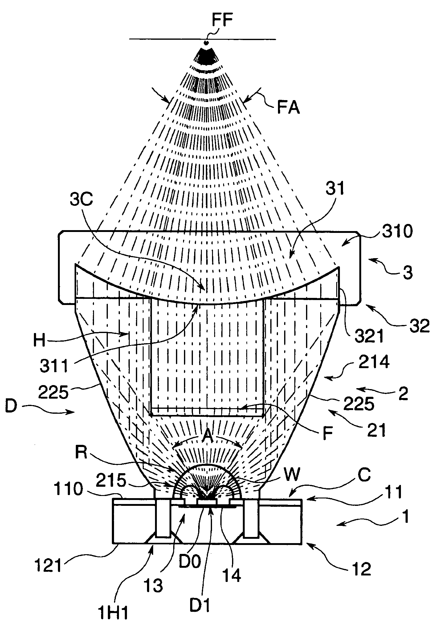
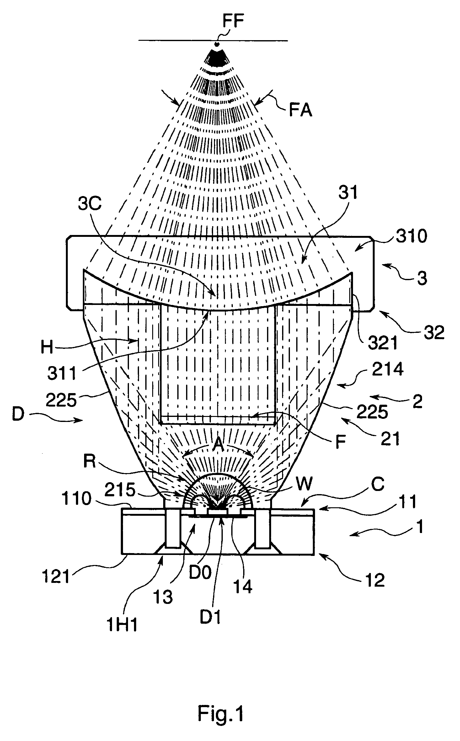
[0044]FIG. 1 is a general structure cross-sectional view of a light emitting diode unit D constituting a system in accordance with an embodiment of the present claimed invention.

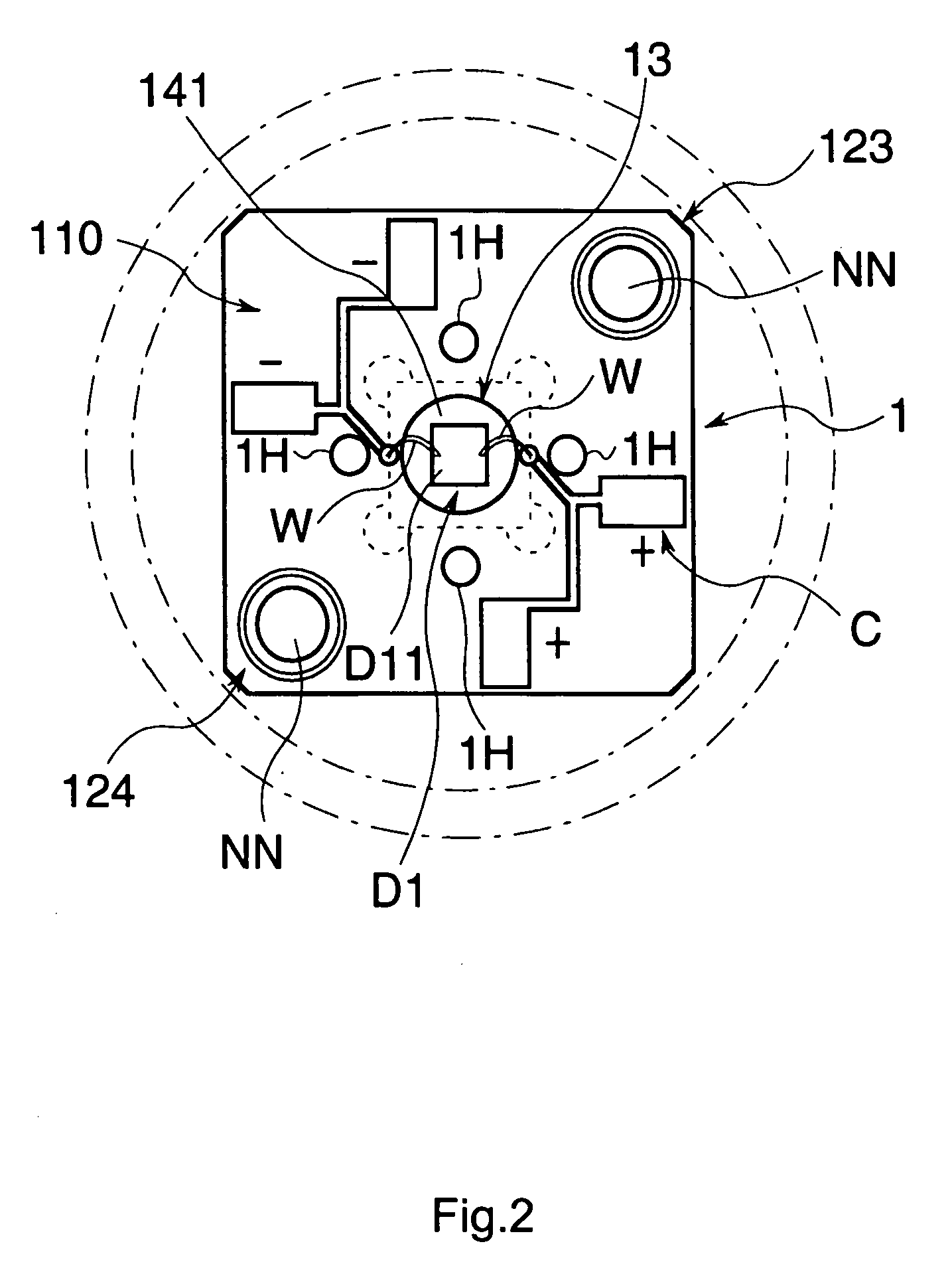
[0045]The light emitting diode unit D comprises a bear element D1 as being a light emitting element to be utilized for, for example, a power LED, a base 1 in a predetermined area of which the bear element D1 is arranged, a first lens 2 that is supported by the base 1 and that transfers emitted light R emitted by the bear element D1 into generally parallel light H traveling toward a desired traveling direction as being a radiation axis P, and a second lens 3 arranged to contact along a distal end portion 220 of the first lens 2.

[0046]In this embodiment, a traveling axis of the parallel light H of the first lens 2 is set as “a radiation axis” and a direction that the light emitting element D1 emits th...


PUM


Abstract

A light emitting diode unit comprises a light emitting element D1, a base 1 having a heat dissipating member 12 that dissipates heat generated by the light emitting element D1, and a first lens 2 comprising a reflecting element 214 that reflects light R2 traveling outside of a predetermined angle among the emitted light R emitted by the light emitting element D1 and a refracting element F that refracts light R1 traveling inside of the predetermined angle among the emitted light R, each of which is formed integrally, with the first lens 2 mounted integrally on the base 1, and the emitted light R emitted from the light emitting element D1 is made to travel generally toward the same direction by the reflecting element 214 and the refracting element F.

Description

FIELD OF THE ART[0001]This invention relates to a light emitting diode unit used for the inspection of an appearance, finish or the detection of flaws in a product.BACKGROUND ART[0002]Conventionally, for a light source of a light emitting diode type used in a light unit for inspection of products or the like, in order to improve the light convergence performance, a bullet-shaped lens to converge the light emitted by a light emitting element is arranged, or a reflector that reflects the light near the light emitting element toward the direction of light emission is arranged near the light emitting element.[0003]However, with light emitting diode units of the above-mentioned arrangement, since the irradiated light from the light emitting element reflects and travels inside the lens portion of the light emitting diode unit, or travels toward the direction of the light emission in a manner other than that would occur from a point source of light, the light emitted from the light emittin...

Claims


Application Information

Patent Timeline
Patent Type & Authority Patents(United States)
IPC IPC(8): F21V7/00F21V5/04H01L33/58H01L33/60H01L33/62
CPCH01L33/58F21V5/04F21V7/0091F21Y2101/02H01L33/54H01L2224/48091H01L33/60H01L2924/00014F21Y2115/10
Inventor YONEDA, KENJIAMANO, TAKAHIROINAGAKI, YASUHIKO
Owner MITSUBISHI CHEM CORP
Why Eureka
Try Eureka