Plumbing fixture seat

a technology for plumbing fixtures and seats, applied in the field of seats, can solve the problems of deformation after prolonged use, seat structure is weak, and the use is not comfortable, and achieves the effects of improving customization ability, being inexpensive to manufacture, and being assembled quite quickly

Active Publication Date: 2012-11-20
KOHLER CO
View PDF31 Cites 10 Cited by
  • Summary
  • Abstract
  • Description
  • Claims
  • Application Information

AI Technical Summary

Benefits of technology

[0015]Similarly, the material selected for the base is not critical. However, since an important purpose of the base is to provide rigidity, the base should preferably be made of a material that is more rigid than a part of (preferably all of) the cushion. We prefer a grade of polypropylene for this purpose that has a high durometer.
[0027]These seats are inexpensive to manufacture using standard molding techniques. For example, injection molding can make the polypropylene base and also the cushion can be an injection molded ethyl vinyl acetate. After formation these parts can be assembled quite quickly (even by a consumer). Further, they permit seats of reduced weight which can still perform the needed functions of the seat, thereby reducing costs and the risk of bowl damage.

Problems solved by technology

While these seats provided good support, they could be uncomfortable when used for an extended period, or when used by particularly sensitive individuals.
However, those seats could be structurally somewhat weak.
Further, they often would deform after prolonged periods of use.
A particularly decorative exterior material may be unsuitable for use in a water environment as being subject to degradation.
Also, desirable external materials may be relatively expensive, thus leading one to want to minimize the thickness of the external layer using that material.
It is generally true that the heavier the seat, the greater the noise that occurs when the seat accidentally drops down onto the toilet (absent a dampering system), and the greater risk of damaging the toilet base when that occurs.
Further, the more material that is used to form the seat, the greater the material cost.

Method used


Image

  • Plumbing fixture seat
  • Plumbing fixture seat
  • Plumbing fixture seat

Examples


second embodiment

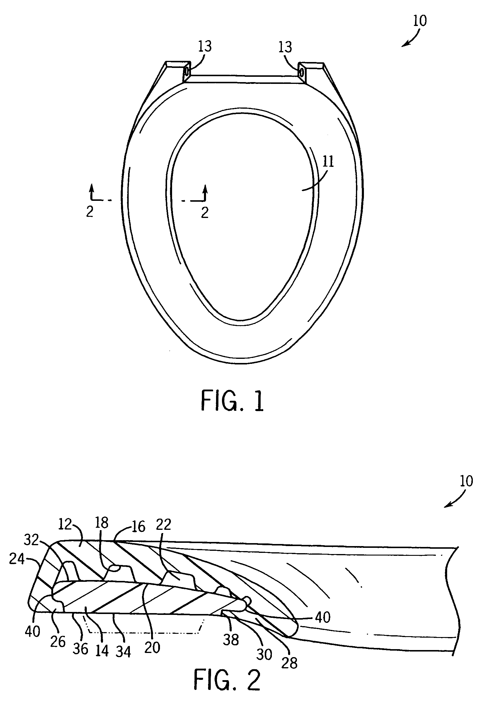
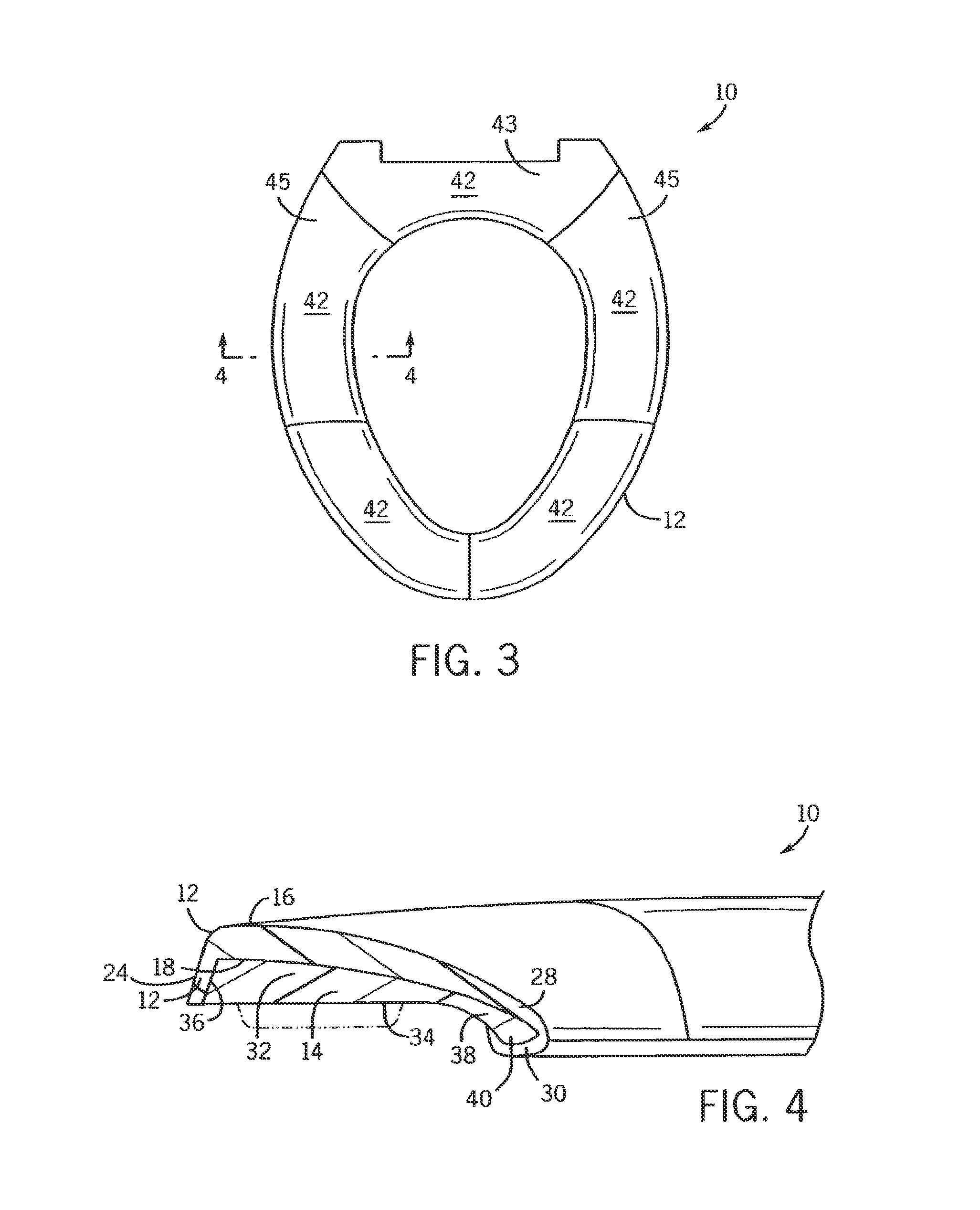
[0048]Referring next to FIGS. 3-4, the plumbing fixture 10 of the present invention is shown. Similar parts are similarly numbered with respect to this embodiment, and with respect to the other embodiments. Note that here there is only one undercut 40, on the radially inward side.

[0049]The cushion 12 in FIG. 3 is comprised of various zones 42 along the circumference. Preferably, the rear zone 43 is made of a more flexible material than the zones 45. In any event, these zones can be selected from materials such as ethyl vinyl acetate, polypropylene, or polythiourethane. Other plastic and synthetic materials may also be selected which have a cushiony feel plus the other desired characteristics for the environment.

[0050]Referring next to FIGS. 5 and 6, the form of snap fit connection is slightly different because of the less slab-like nature of the base. Groove 44 shows that some weight can be reduced in this configuration.

[0051]As seen in FIG. 7 the air pockets can be removed, and if ...

embodiment 50

[0056]In FIG. 13 we show another embodiment 50 where the zonal regions 51 and 52 extend along the thigh area and part of the buttocks area, rather than simply being defined by radial severing lines.


PUM

PropertyMeasurementUnit
flexibleaaaaaaaaaa
hardaaaaaaaaaa
thicknessaaaaaaaaaa

Abstract

Disclosed are cushioned toilet seats. They have an upper cushion supported on a more rigid base. The base may be removably connected to the cushion via a snap-fit connection, and the cushion can include zones having different durometers around its circumference. The upper cushion may have flexible support legs that extend into a cavity between the base and cushion. In other forms a kit is provided to allow the upper cushion of the seat to be customized by the consumer.

Description

CROSS-REFERENCE TO RELATED APPLICATION[0001]Not applicable.STATEMENT OF FEDERALLY SPONSORED RESEARCH OR DEVELOPMENT[0002]Not applicable.BACKGROUND OF THE INVENTION[0003]The present invention relates to seats mountable on toilets, bidets and the like. In particular it relates to such seats which have been modified for improved comfort, and provided with structures permitting customization of the seat.[0004]A wide variety of toilet seats have been developed, typically in the form of rings with central holes, or horseshoe shaped structures with the opening of the horseshoe projecting forward. Many of the earlier toilet seats were made of wood or another hard material. Later seats were made of hard plastics. While these seats provided good support, they could be uncomfortable when used for an extended period, or when used by particularly sensitive individuals.[0005]As a result the art developed a variety of cushioned toilet seats. Some of these were made of a single material which had c...

Claims


Application Information

Patent Timeline
Patent Type & Authority Patents(United States)
IPC IPC(8): A47K13/00
CPCA47K13/00A47K13/02
Inventor VIERKANT, III, ERICH C.KAULE, BRIAN M.
Owner KOHLER CO
Why Eureka
Try Eureka