Method and system for protecting privacy of signature on mail ballot utilizing optical shutter

a technology of optical shutter and mail ballot, applied in the field of voting systems, can solve the problems of increasing the risk of accidental tear of envelopes, increasing the risk of envelope damage, so as to reduce the risk of damage to ballots, reduce processing costs, and reduce the risk of damage.

Inactive Publication Date: 2008-05-29
PITNEY BOWES INC
View PDF18 Cites 10 Cited by
  • Summary
  • Abstract
  • Description
  • Claims
  • Application Information

AI Technical Summary

Benefits of technology

[0006]The present invention alleviates the problems associated with the prior art and provides methods and systems that protect the privacy of signatures on ballots sent through the mail while also reducing the risk of damage to the ballots when the signatures are revealed.
[0007]In accordance with the present invention, the envelope for returning ballots by mail includes an electronic optical shutter that covers an opening in the flap of the envelope. The voter signs the back of the envelope in an area that will be visible through the opening in the flap (covered by the optical shutter) when the envelope flap is sealed. The optical shutter is opaque under static conditions, but will become transparent when appropriate power is supplied to it. Thus, when the envelope flap is sealed and no power is applied to the optical shutter, the voter's signature will be concealed by the optical shutter. Upon receipt at the registrar's office (or other official vote tallying location), the optical shutter can be powered, thereby rendering the optical shutter transparent, and the voter's signature can be viewed for comparison with the official records to perform the required signature verification to determine validity and authenticity of the ballot. Preferably, the envelope flap is provided with conductive power rails that will allow power to be supplied to the optical shutter while the envelope is being processed by automated mail processing equipment. Thus, while the envelope is en route from the voter to the registrar's office, the voter's signature will be concealed from plain view. Viewing of the signature does not require any mechanical manipulation of the envelope or flaps on the envelope, thereby reducing the processing cost and the risk of causing damage to the ballot contained therein. After verification of the voter's signature, the ballot can be separated from the envelope and provided to the ballot counters for tabulation. Optionally, the optical shutter can be reused on subsequent envelopes.

Problems solved by technology

One general problem with vote by mail envelopes is the signature is in the open and exposed for all to see throughout the process for determining whether or not the vote is authentic.
This leads to potential privacy issues and concerns, e.g., fraudulent usage of a voter's signature.
These solutions, however, require some mechanical manipulation of the envelopes, which is both expensive and increases the risk of accidental tears of the envelope, potentially leading to damage to the ballots contained in the envelopes and subsequently errors in the counting of votes.

Method used


Image

  • Method and system for protecting privacy of signature on mail ballot utilizing optical shutter
  • Method and system for protecting privacy of signature on mail ballot utilizing optical shutter
  • Method and system for protecting privacy of signature on mail ballot utilizing optical shutter

Examples


Embodiment Construction

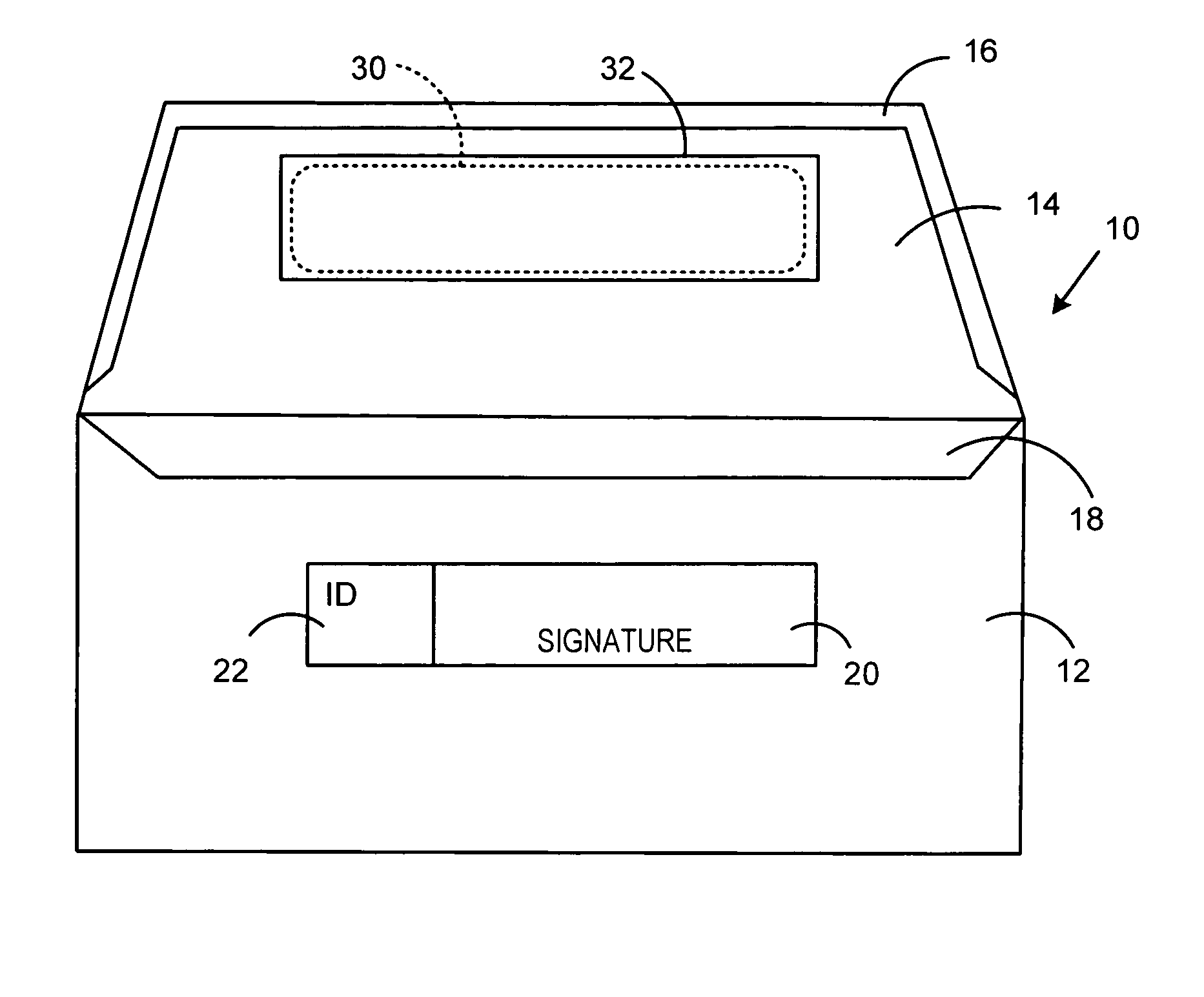
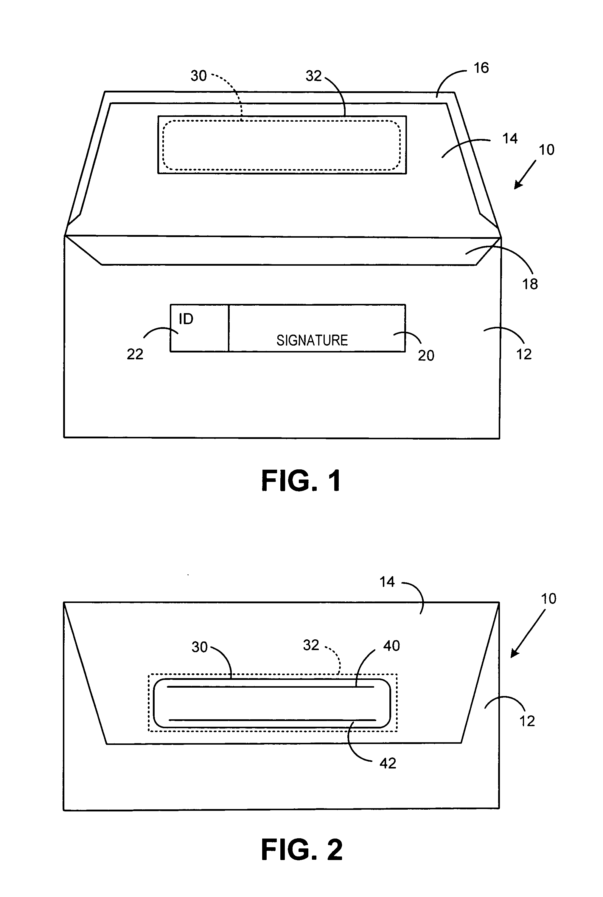
[0015]In describing the present invention, reference is made to the drawings, wherein there is seen in FIG. 1 an envelope 10 for returning ballots by mail according to an embodiment of the present invention in an open position. While the present description is directed to an envelope for returning ballots by mail, it should be understood that the invention is not so limited and the envelope 10 could be used to hold any type of communication or material. Envelope 10 includes a body portion 12 and a flap portion 14 connected to the body portion 12. When the flap portion 14 is in an open position as illustrated in FIG. 1, contents, such as, for example, a ballot, can be inserted into a pocket 18 formed by the body portion 12. The flap portion 14 can then be moved to a closed position (as illustrated in FIG. 2), and sealed utilizing a glue or sealing strip 16 which when activated will adhere the flap portion 14 to the body portion 12, thereby covering the pocket 18 and preventing the co...


PUM


Abstract

Methods and systems that protect the privacy of signatures on envelopes containing ballots sent through the mail are provided. The envelope for returning ballots by mail includes an electronic optical shutter that covers an opening in the flap of the envelope. The voter signs the back of the envelope in an area that will be visible through the opening in the flap (covered by the optical shutter) when the envelope flap is sealed. The optical shutter is opaque under static conditions, but will become transparent when power is supplied to it. When the envelope flap is sealed and no power is applied to the optical shutter, the voter's signature will be concealed by the optical shutter. Upon receipt at the registrar's office, the optical shutter can be powered, thereby rendering the optical shutter transparent, and the voter's signature can be viewed.

Description

FIELD OF THE INVENTION[0001]The invention disclosed herein relates generally to voting systems, and more particularly to a method and system for protecting privacy of signatures on ballots sent through the mail.BACKGROUND OF THE INVENTION[0002]In democratic countries, governmental officials are chosen by the citizens in an election. Conducting an election and voting for candidates for public office in the United States can be performed in several different ways. One such way utilizes mechanical voting machines at predetermined polling places. When potential voters enter the predetermined polling place, voting personnel verify that each voter is properly registered in that voting district and that they have not already voted in that election. Thus, for a voter to cast his vote, he must go to the polling place at which he is registered, based on the voter's residence. Another method for conducting an election and voting utilizes paper ballots that are mailed to the voter who marks the...

Claims


Application Information

Patent Timeline
Patent Type & Authority Applications(United States)
IPC IPC(8): B65D27/04
CPCB65D27/04B65D27/00
Inventor QUINE, DOUGLAS B.RYAN, FREDERICK W.
Owner PITNEY BOWES INC
Why Eureka
Try Eureka