Device for implementing a cutting balloon intervention with IVUS monitoring

Active Publication Date: 2005-10-06
SIEMENS HEALTHCARE GMBH
21 Cites 66 Cited by

AI-Extracted Technical Summary

Problems solved by technology

The compression of large quantities of plaque may result in damage to the inner vascular wall, leading to an increased restenosis rate.
A significant disadvantage of the method is the additional process stage and the additional costs for the stent.
The drawback of this method is that the coronary arteries are only shown in two dimensions and only the actual stenosis is shown on the x-ray image.
During the intervention it is difficult for medical staff to distinguish between pla...

Benefits of technology

[0013] The object of the invention is therefore to configure a device of the type specified above, to provide an optimum device which is easy to use and which enabl...

Abstract

Device for implementing a cutting balloon intervention by means of a “cutting balloon” catheter, at the distal end of which is disposed an inflatable balloon with axially running blades mounted thereon, and which has IVUS monitoring, whereby the cutting balloon catheter is combined with an IVUS catheter to form an integrated module.

Application Domain

Guide needlesStents +7

Technology Topic

Balloon catheterCatheter device +1

Image

  • Device for implementing a cutting balloon intervention with IVUS monitoring
  • Device for implementing a cutting balloon intervention with IVUS monitoring
  • Device for implementing a cutting balloon intervention with IVUS monitoring

Examples

  • Experimental program(1)

Example

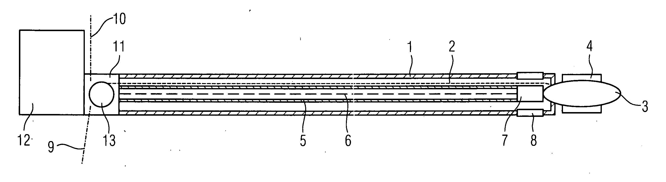
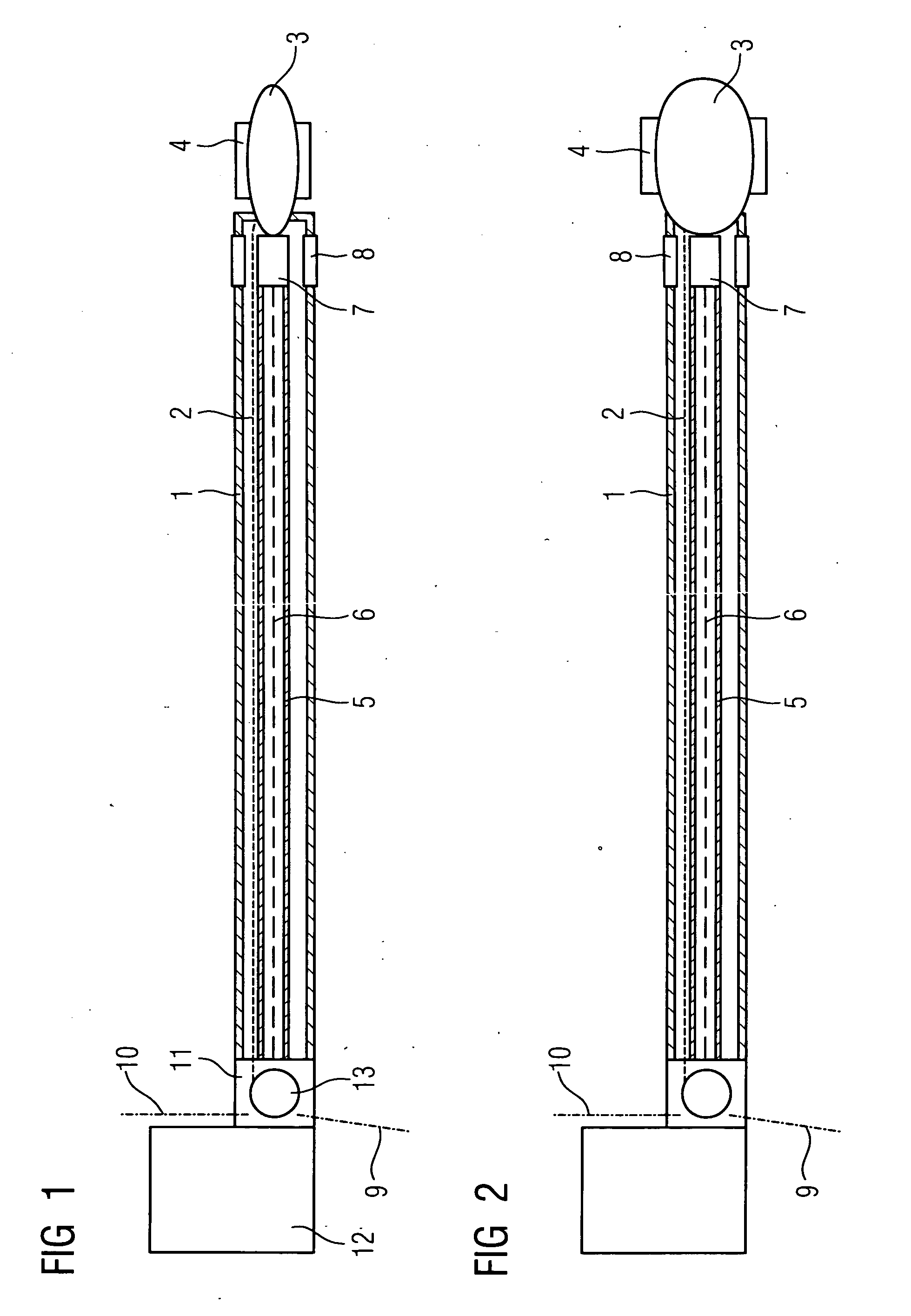
[0041] On the basis of FIG. 1 and 2 it is possible to identify, in a basic schematic diagram, the construction and functionality of the cutting-balloon catheter with integrated IVUS monitoring to be used for stenosis removal according to the invention. An inflation line 2 for inflating the cutting balloon 3 that is fastened at the distal end of the flexible catheter sheath 1, is disposed within said catheter sheath 1, with a plurality—in particular three or four—of cutting blades 4, being mounted on the outer surface of said cutting balloon and arranged in a manner essentially parallel to the axis. When the balloon is inflated these blades 4 make longitudinal incisions into the vascular deposits, or “shave” plaque from the vascular wall, before the coronary artery is dilated by the balloon.
[0042] In addition to the inflation line 2 the flexible catheter sheath 1 also accommodates a hollow flexible drive shaft 5 accommodating an IVUS signal line 6 for an IVUS sensor 7, said IVUS sensor 7 being disposed directly behind the cutting balloon 3 within a ring-shaped, ultrasound-transparent window 8 in the catheter sheath 1. A connection for contrast media and possibly irrigation fluid, which can be pumped through the catheter sheath 1 to an outlet opening (not shown) in the vicinity of the ring-shaped window 10, is indicated by 9. 10 indicates the connection line for delivery of pressure gas or pressure fluid to the inflation line 2 for the cutting balloon.
[0043] The combined IVUS catheter with cutting balloon is connected to the signal interface and the drive unit 12 for the IVUS system via the mechanical connection system 11. This mechanical connection system 11 incorporates a rotating coupling 13 for the connections.
[0044] By feeding the pressure medium in via the line 10 and the inflation line 2, the balloon is inflated from the position at insertion according to FIG. 1 to the position shown in FIG. 2, after being advanced to the point of intervention in the vessel, whereby longitudinal sections are first incised into the vascular deposits by the cutting blades 4, before the vessel—in particular a coronary artery—is dilated by the inflating balloon. This causes the plaque to flake off.
[0045] In the modified exemplary embodiment shown in FIGS. 3 and 4, the IVUS sensor 7 is disposed forward of the cutting balloon 3′, which is configured here as a ring-shaped balloon. This means that the hollow, flexible drive shaft 5 for the IVUS sensor 7, with the IVUS signal line 6 disposed therein, runs through the ring-shaped balloon, which—as before—is fastened to the catheter sheath 1. In the embodiment shown, the IVUS sensor is located inside a ring-shaped window 8′ in the hollow, flexible drive shaft 5.
[0046] To reduce the degree by which the rotation of the drive shaft 5 for the IVUS sensor, which runs through this cutting balloon 3′, is restricted by the fixed position of the balloon, provision is made in the exemplary embodiment according to FIGS. 5 and 6 (as compared to the exemplary embodiment according to FIGS. 3 and 4) for the cutting balloon 3 not simply to be disposed freely at the distal end of the catheter sheath 1, but on a tapered, rigid section la running through the cutting balloon 3′, whereby the hollow, flexible drive shaft 5 for the distally disposed IVUS sensor 7 is accommodated so as to move freely in said tapered, rigid section. As a result, the drive shaft 5 does not move against the inner wall of the ring shaped cutting balloon with correspondingly high friction, but against the rigid section I a of the catheter sheath 1′, said rigid section having been designed to ensure low friction, especially since this section cannot be additionally pressed against the drive shaft 5 by the inflation pressure of the cutting balloon, as in the previous exemplary embodiment.
[0047] The exemplary embodiment according to FIG. 7 essentially differs from that shown in FIGS. 1 to 6 in that no rotating IVUS sensor 7 is provided. Instead, a circumferential sensor array 7′ integrated in the catheter sheath 1 and comprising a plurality of ultrasound transducers 14 distributed equidistantly around its circumference, whereby said ultrasound transducers can be controlled, with staggered timing, via the IVUS signal line 6, and can function simultaneously as transmitters and receivers. This use of a sensor array instead of a rotating IVUS sensor means, of course, that the hollow, flexible drive shaft 5 of the previous exemplary embodiments is no longer required.
[0048] This also applies for the embodiment according to FIG. 8, which represents a modification compared to FIG. 7, whereby the IVUS sensor is formed by a sensor array 7′ disposed forward of the cutting balloon 3′, which, in turn, is configured here as a ring-shaped balloon. This sensor array is disposed at the distal end of the tapered front section 1a of the catheter sheath 1, on which, in turn, the ring-shaped cutting balloon 3′ is mounted.
[0049] The invention is not limited to the exemplary embodiments shown. Thus magnetic navigation would also be possible, with permanent magnets or—alternatively—with electromagnets on the catheter tip or on the catheter, whereby these magnets and their position are not shown in the diagrams. In addition, an inflatable balloon—preferably even with several chambers—could be used in the vicinity of the tip, in order to bring the catheter tip to the required position and keep it there during the intervention, and—if possible—also to be used additionally as a dilatation balloon. This balloon is likewise not shown in the drawings. Furthermore, x-ray markers that are known per se could be provided on the catheter shaft, and also—of course—openings for a guidewire. Finally, it may be noted that the proposed solution of a combined IVUS catheter with cutting balloon for the removal of complete stenoses is not limited to use in coronary arteries, but is essentially suitable for all types of vessels in the body.

PUM

no PUM

Description & Claims & Application Information

We can also present the details of the Description, Claims and Application information to help users get a comprehensive understanding of the technical details of the patent, such as background art, summary of invention, brief description of drawings, description of embodiments, and other original content. On the other hand, users can also determine the specific scope of protection of the technology through the list of claims; as well as understand the changes in the life cycle of the technology with the presentation of the patent timeline. Login to view more.

Similar technology patents

Household appliance control method and device and mobile terminal

InactiveCN103605531Aeasy to operateeasy to use
Owner:GD MIDEA AIR-CONDITIONING EQUIP CO LTD +1

Multi-stage oral-fluid testing device

ActiveUS20160121322A1easy to use
Owner:PREMIER BIOTECH LLC

System and method of monitoring temperature

InactiveUS7140768B2less susceptible to tampereasy to use
Owner:COLD CHAIN TECH

Classification and recommendation of technical efficacy words

  • easy to use
Why Eureka
Try Eureka