Preparation of a component for use in a joint

a technology for components and joints, applied in the field of preparation of components, can solve the problems of large weight increase, de-lamination around fastener holes, and the tendency of fastener joints to be particularly weak, and achieve the effect of reducing the risk of de-lamination

Active Publication Date: 2010-03-18
AIRBUS OPERATIONS LTD
View PDF9 Cites 58 Cited by
  • Summary
  • Abstract
  • Description
  • Claims
  • Application Information

AI Technical Summary

Benefits of technology

[0033]The second component may be a laminar component formed in a series of layers. In this case, the projections reduce the risk of de-laminati...

Problems solved by technology

Joining between composite and metallic or thermoplastic components is currently approached in a number of ways, each with its own limitations.
The use of fasteners is commonplace but tends to result in de-lamination around fastener holes, as well as the associated difficulties of drilling holes in composites such as Carbon Fibre and Aramids such as Kevlar.
This results in a requirement for significant reinforcement around fastener holes, leading to a large weight increase, which is particularly undesirable in aerospace applications.
Fastened joints tend to be particularly weak in the pull-through direction (that is, the direction of axial load through the fastener) and as such are not well suited to aerospace applications such as fastening ribs to covers, where air and fuel pressure loads tend to result in significant axial component of load through the fastener.
Adhesive bonds are an increasingly common means of joining metallic components to composite laminates, however these perform poorly in peel, tension and cleavage, and tend to fail with little or no warning.
Their weakness i...

Method used


Image

  • Preparation of a component for use in a joint
  • Preparation of a component for use in a joint
  • Preparation of a component for use in a joint

Examples


Embodiment Construction

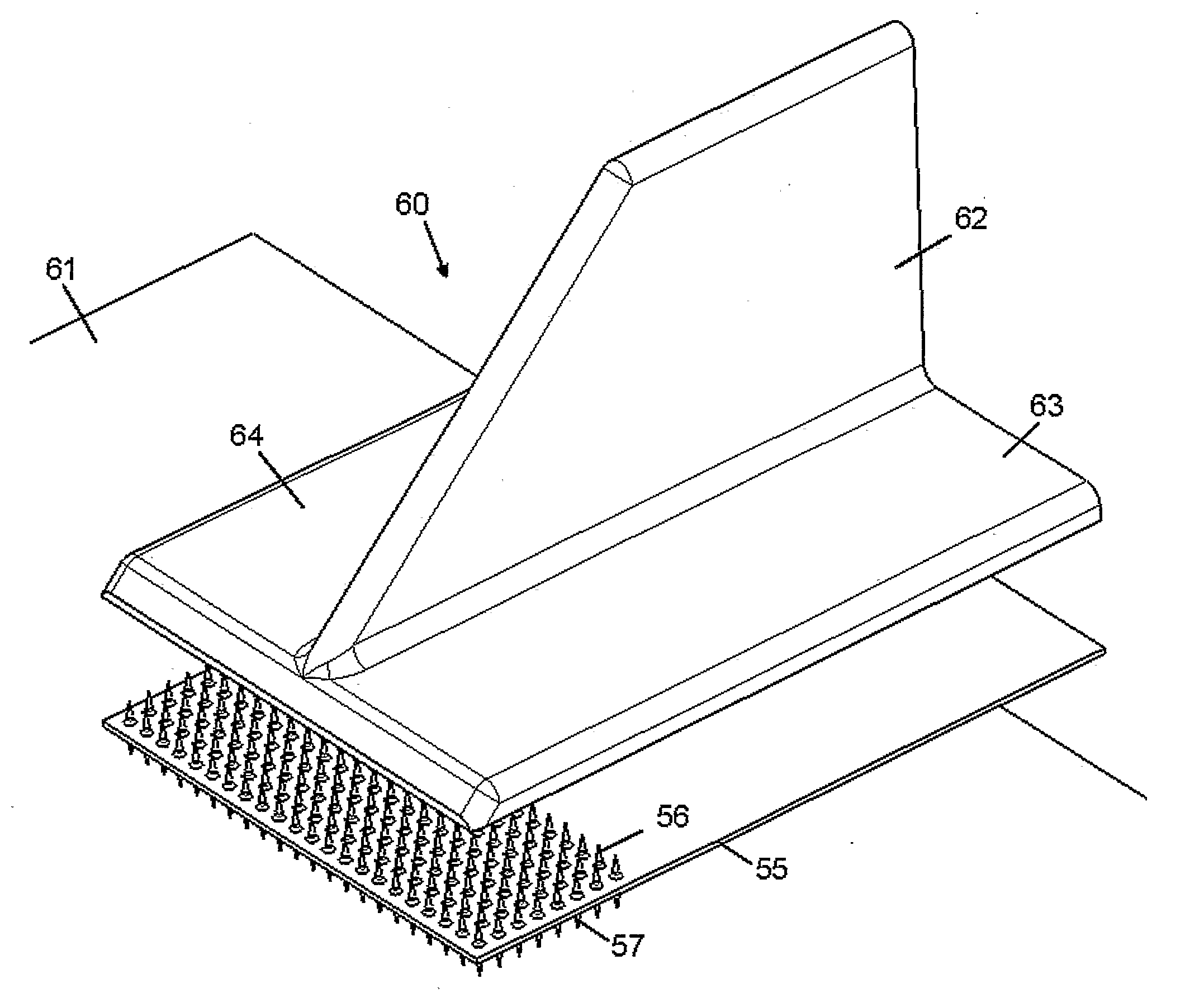
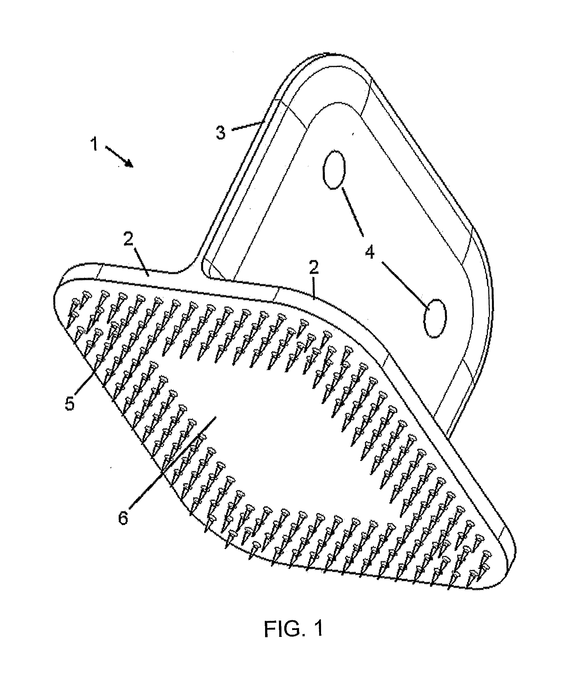
[0056]A metallic floating rib foot 1 shown in FIG. 1 comprises a web portion 3 and a pair of flanges 2. The web portion 3 has a pair of fastener holes 4. An array of projections 5 extend from the underside of the flanges 2. As can be seen in FIG. 1, the projections 5 are distributed evenly over a bond region which extends around the periphery of the flanges 2 and surrounds a central region 6 with no projections.

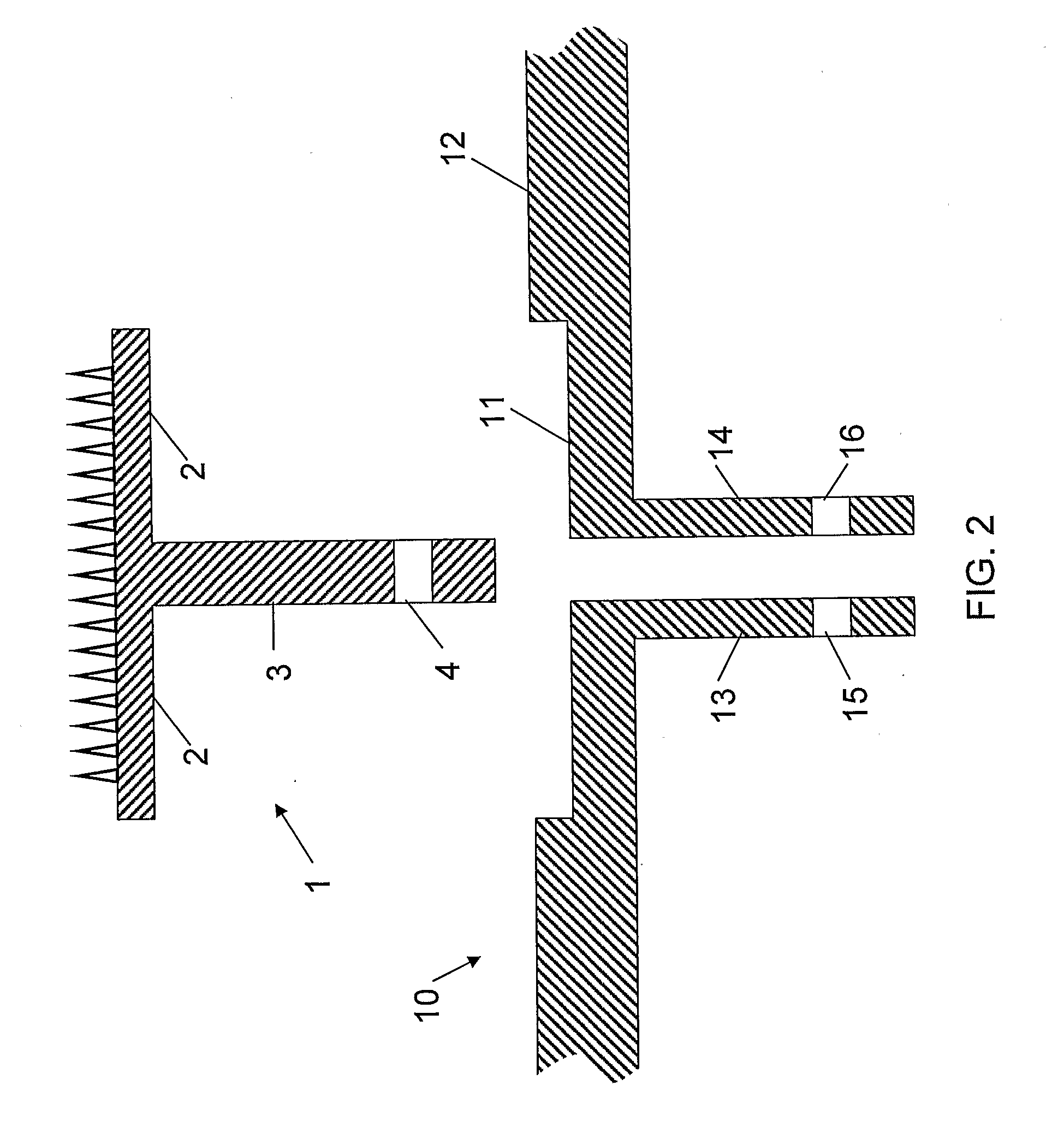
[0057]The floating rib foot 1 is integrated into a mould tool 10 as shown in FIG. 2. The mould tool 10 has a mould surface 12 with a recess 11 which receives the flanges 2 as shown in FIG. 3. Web portion 3 extends into a channel between a pair of plates 13, 14, and is secured in place by a fastener 17 passing through a pair of holes 15, 16 in the plates 13, 14 as shown in FIG. 3. In the example of FIG. 3 only one fastener 17 is shown, but in alternative arrangements two or more fasteners may be used to secure the floating rib foot to the mould tool. In the case where two fast...


PUM

PropertyMeasurementUnit
Widthaaaaaaaaaa
Heightaaaaaaaaaa
Metallic bondaaaaaaaaaa

Abstract

A method of preparing a component (60) to be joined to another component (55). The method comprises growing an array of projections (56, 57) on a bond region of the component (55) in a series of layers, each layer being grown by directing energy and/or material from a head to selected parts of the bond region. The joint may be used to join a pair of structural components, for instance in an aerospace application. For instance the joint may be used to join a reinforcing plate, floating rib foot, or stringer to a panel such as a wing or fuselage cover. Alternatively the joint may be used to join adjacent layers in a laminate structure.

Description

FIELD OF THE INVENTION[0001]The present invention relates to a method of preparing a component to be joined to another component; a component prepared by such a method; and a joint including such a component.BACKGROUND OF THE INVENTION[0002]Joining between composite and metallic or thermoplastic components is currently approached in a number of ways, each with its own limitations.[0003]The use of fasteners is commonplace but tends to result in de-lamination around fastener holes, as well as the associated difficulties of drilling holes in composites such as Carbon Fibre and Aramids such as Kevlar.[0004]The bearing strength of laminated composites tends to be low, as does the inter-laminar shear strength. This results in a requirement for significant reinforcement around fastener holes, leading to a large weight increase, which is particularly undesirable in aerospace applications.[0005]Fastened joints tend to be particularly weak in the pull-through direction (that is, the direction...

Claims


Application Information

Patent Timeline
IPC IPC(8): B32B7/08B29C65/56B23K26/34C09J5/02F16B5/07
CPCB23K15/0086Y10T428/24521C09J5/02F16B5/07B23K26/3206B23K26/322B23K26/3246B23K26/328B22F3/24B29C65/64B29C66/742B22F2005/005B22F7/04B29C66/30321B22F3/1055B22F5/00Y10T428/24008B23K26/34B22F7/08B33Y80/00B33Y10/00B23K26/32B23K26/324B29C65/645B29C66/1122B29C66/45B29C66/474B29C66/721B29C66/7212B29C66/73751B29C66/7394B29C65/02B29C65/564B29C66/7392B29C65/72B29C66/30341B29C65/06B29C66/71B29C64/153B23K2103/05B23K2103/16B23K2103/30B23K2103/42B23K2103/50Y10T403/472B23K2103/14B23K2103/18Y10T428/24802Y10T428/24917Y02P10/25B22F10/73B22F10/40B22F10/25B22F12/63B22F10/28B22F10/385B29K2307/04B29K2063/00B23K26/323F16B5/08
Inventor MEYER, JONATHAN
Owner AIRBUS OPERATIONS LTD
Why Eureka
Try Eureka