Enclosed blind control

a blind control and enclosed technology, applied in the field of blind control, can solve the problems of unsafe conditions, uncontrollable elements, and dislodged pulleys from buildings, and achieve the effect of greater mechanical advantages

Active Publication Date: 2018-06-21
MAXXMAR
View PDF3 Cites 6 Cited by
  • Summary
  • Abstract
  • Description
  • Claims
  • Application Information

AI Technical Summary

Benefits of technology

[0030]There may be a separate winding handle for the rotary driver. The handle may be attached to one side or to the other, and may have an extension extending radially out to provide greater mechanical advantage.

Problems solved by technology

However safety considerations for some time have been forcing Government agencies seek further ways to restrict unsafe or unwanted access to the endless loop type of control element.
However such a pulley may become dislodged or loosened from the building to which it was attached.
The guide pulley will then hang loose on the loop of the element, leaving the element uncontrolled, as before.
This led to accidents and unsafe conditions.
In other cases the pulley might have been installed incorrectly.
One of the problems in simply attaching the lower end of the loop to a pulley, is that the pulley, in whatever form it took, was attached to the window frame.
This may have been an inconvenience to many.
This proposal still does not meet the problem of safety.
It would not satisfy the requirements for safety.

Method used


Image

  • Enclosed blind control
  • Enclosed blind control
  • Enclosed blind control

Examples


Embodiment Construction

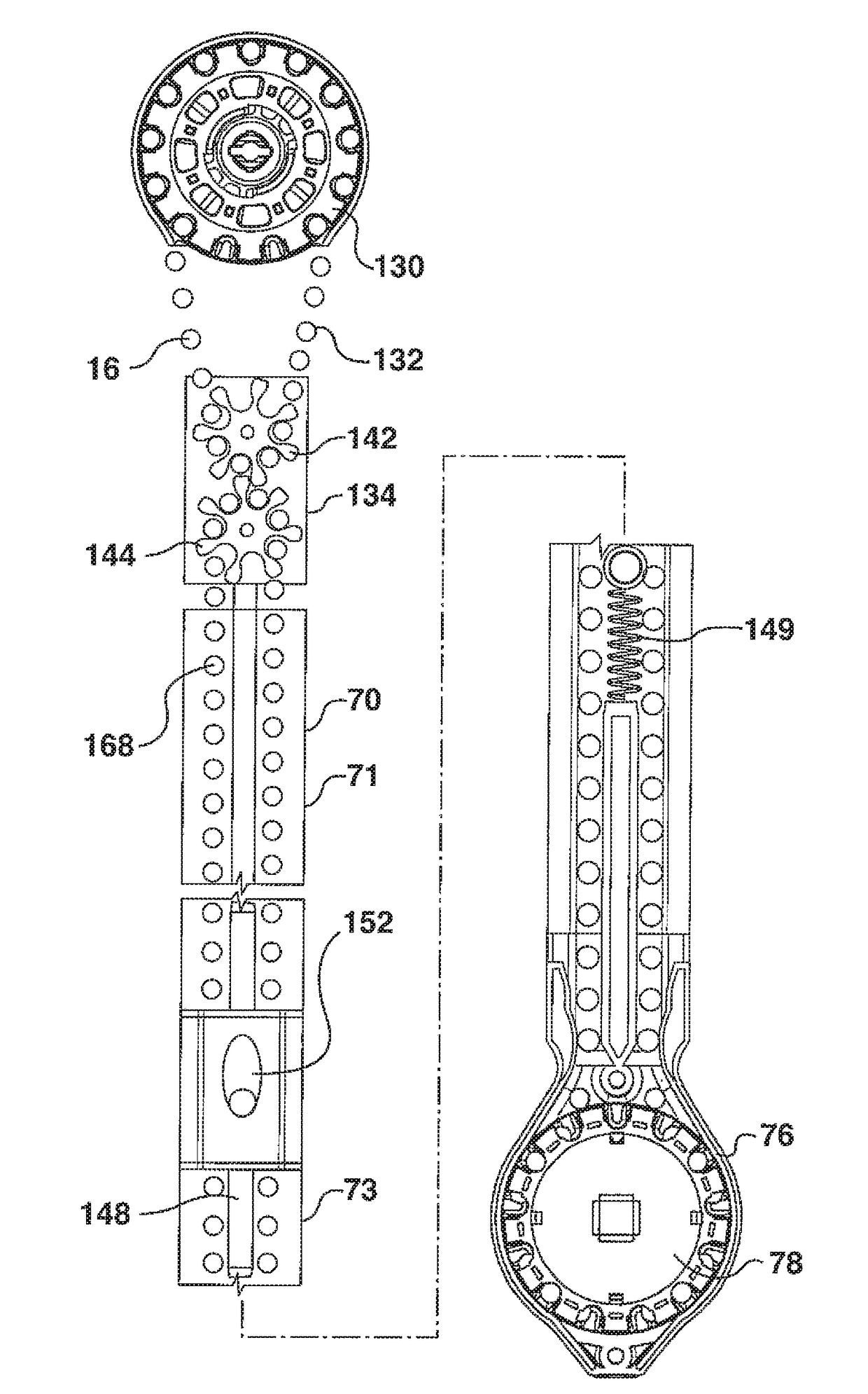
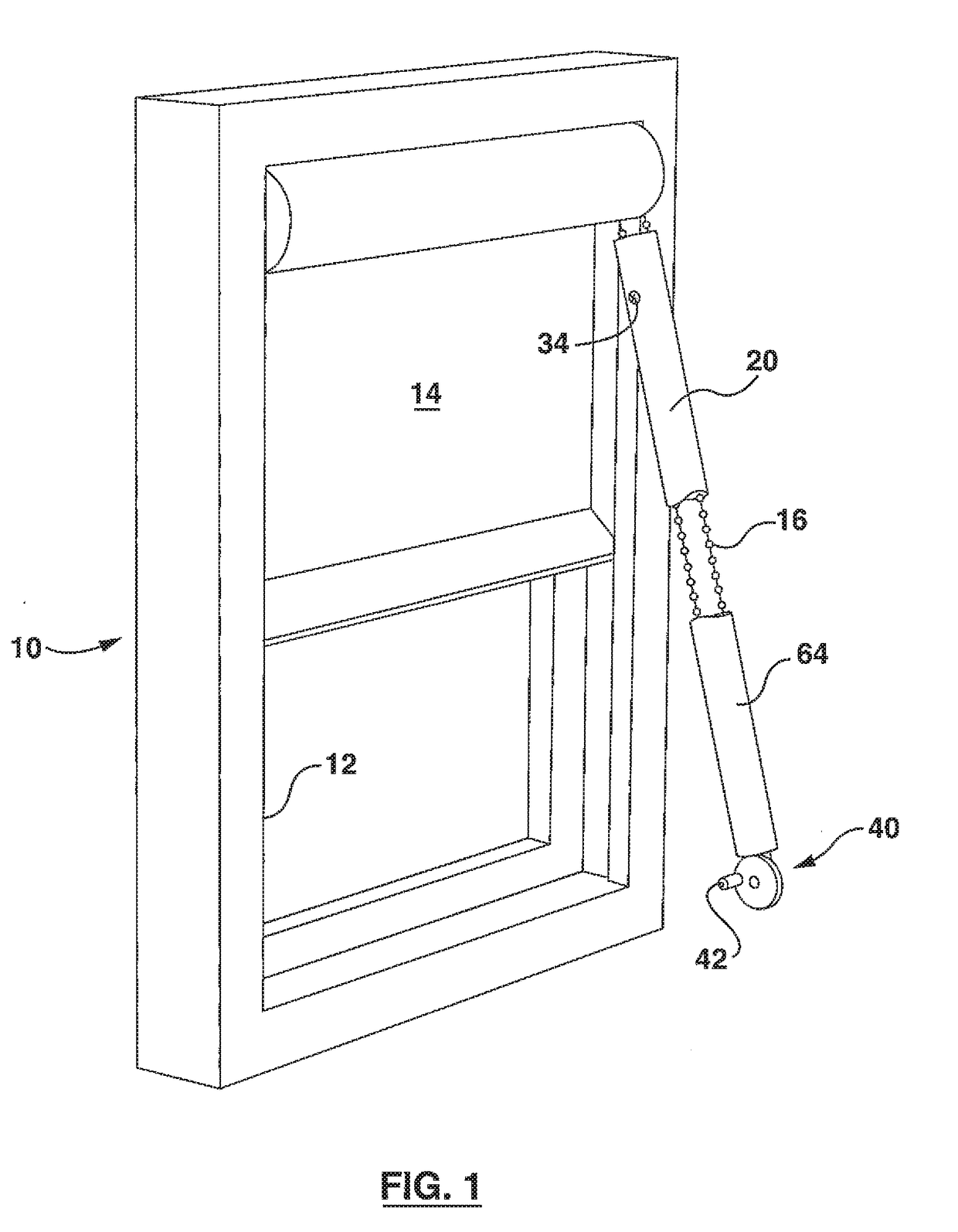
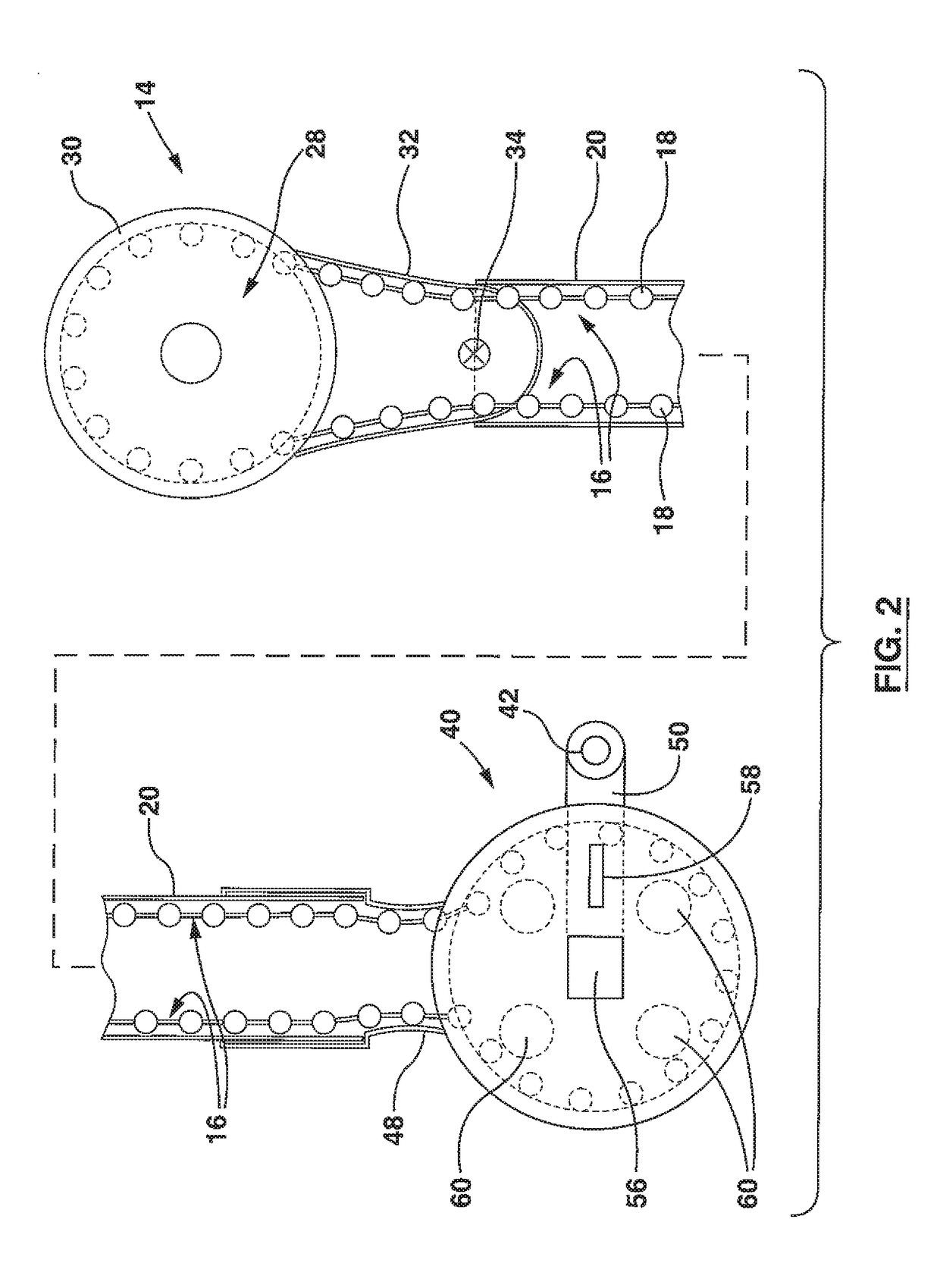
[0068]Referring first to FIG. 1, it will be seen that a simple window, 10 representing a building opening, has a typical border frame 12. A simple roller blind 14 is shown mounted on the frame. The blind, in this example, is a sheet of suitable material wound onto a roller, from which the sheet or blind may be lowered and raised. The roller is operated, in this case, by a safety blind control element 16. The element, in this example is shown as the typical chain type of element, with a series of balls 18 connected by wire or other filament material, in an endless chain. This element runs around a well known form of sprocket gear drive (not shown) in the mechanism of the blind 14.

[0069]There will usually be some form of clutch (not shown) associated with the blind. This purpose is to prevent the blind from unwinding on its own.

[0070]Such features are very well known in the industry and require no illustration.

[0071]As is usual the element 16 is an endless loop. Pulling one side of th...


PUM


Abstract

A blind having a blind operating mechanism and a blind control element and having an enclosure for the blind control element, with the element completely enclosed, a connector supporting the enclosure on the blind, and depending downwardly, and a drive device at the lower end of the enclosure for operating the element.

Description

[0001]This application is based on U.S. provisional application Ser. 62 / 430,668 title Enclosed Blind Control inventor Norbert Marocco filed Dec. 6, 2016, the priority of which is claimed.FIELD OF THE INVENTION[0002]The invention relates to a blind having a blind control element and an enclosure for the blind control element preventing unsafe, or unwanted access to the blind control element, and providing a means for operating the blind control elementBACKGROUND OF THE INVENTION[0003]Blinds for building openings, eg windows, doors and the like, may be operated either simply down and up, in the case of eg. roller blinds, or in the case of eg. vertical shade panels, the vertical shade panels may be rotated open or closed.[0004]The control elements for these blind operations are usually in the form of an endless cord or chain. The control element simply hangs down along one side of the building opening, in an endless loop.[0005]Other forms of blinds and window coverings may also be oper...

Claims


Application Information

Patent Timeline
Patent Type & Authority Applications(United States)
IPC IPC(8): E06B9/322E06B9/326E06B9/78F16H7/06F16H37/02
CPCE06B9/322E06B2009/785E06B9/78E06B9/326
Inventor MAROCCO, NORBERT
Owner MAXXMAR
Why Eureka
Try Eureka