Latching device and method

a technology of latching device and latching seal, which is applied in the direction of carpet fasteners, lighting and heating apparatus, domestic cooling devices, etc., can solve the problems of ice accumulation, difficult compression of gaskets, and the latch itself does not provide a positive indication, so as to achieve easy and reliable latching and sealing, and enhance security. the effect of the mechanical advantag

Inactive Publication Date: 2002-06-20
THERMO ELECTRON A DE
View PDF0 Cites 1 Cited by
  • Summary
  • Abstract
  • Description
  • Claims
  • Application Information

AI Technical Summary

Benefits of technology

0008] The present invention provides a latching assembly mountable on a panel for securing the panel to a frame. The latching assembly of the present invention can provide greater mechanical advantage when the latching assembly is closed or open, in comparison with prior art assemblies, permitting refrigerator and freezer doors to be easily and reliably latched and sealed when misalignment occurs or the gasket compression is compromised. The latching assembly of the present invention also can provide enhanced security in comparison with prior art devices, because the assembly in some embodiments provides a key lock and slots where a padlock may be inserted. The key lock and padlock may be used in conjunction with one another or separately to prevent the latch assembly from opening.

Problems solved by technology

A disadvantage of some known latching devices is that the latch itself does not provide a positive indication of when the door is fully latched.
Another problem with many known latch designs is that the gasket may be made of silicon or PVC which tends to absorb moisture and freeze making the gasket more difficult to compress ("stiffen").
Ice accumulates on the gasket, obstructing the seal and contributing to gasket compression difficulties.
Another problem with many prior art designs is that if the first panel becomes misaligned with the corresponding second panel or frame due to manufacturing defects or normal wear, the latch may be unable to accommodate the misalignment and become inoperable.
Due to the misalignment, the panels or frame must be physically aligned, requiring costly maintenance visits.
Similarly, there is a need for latching assembly which seals the door to the frame even when the gasket is obstructed by foreign bodies or the gasket is hardened and difficult to compress.

Method used


Image

  • Latching device and method
  • Latching device and method
  • Latching device and method

Examples


Embodiment Construction

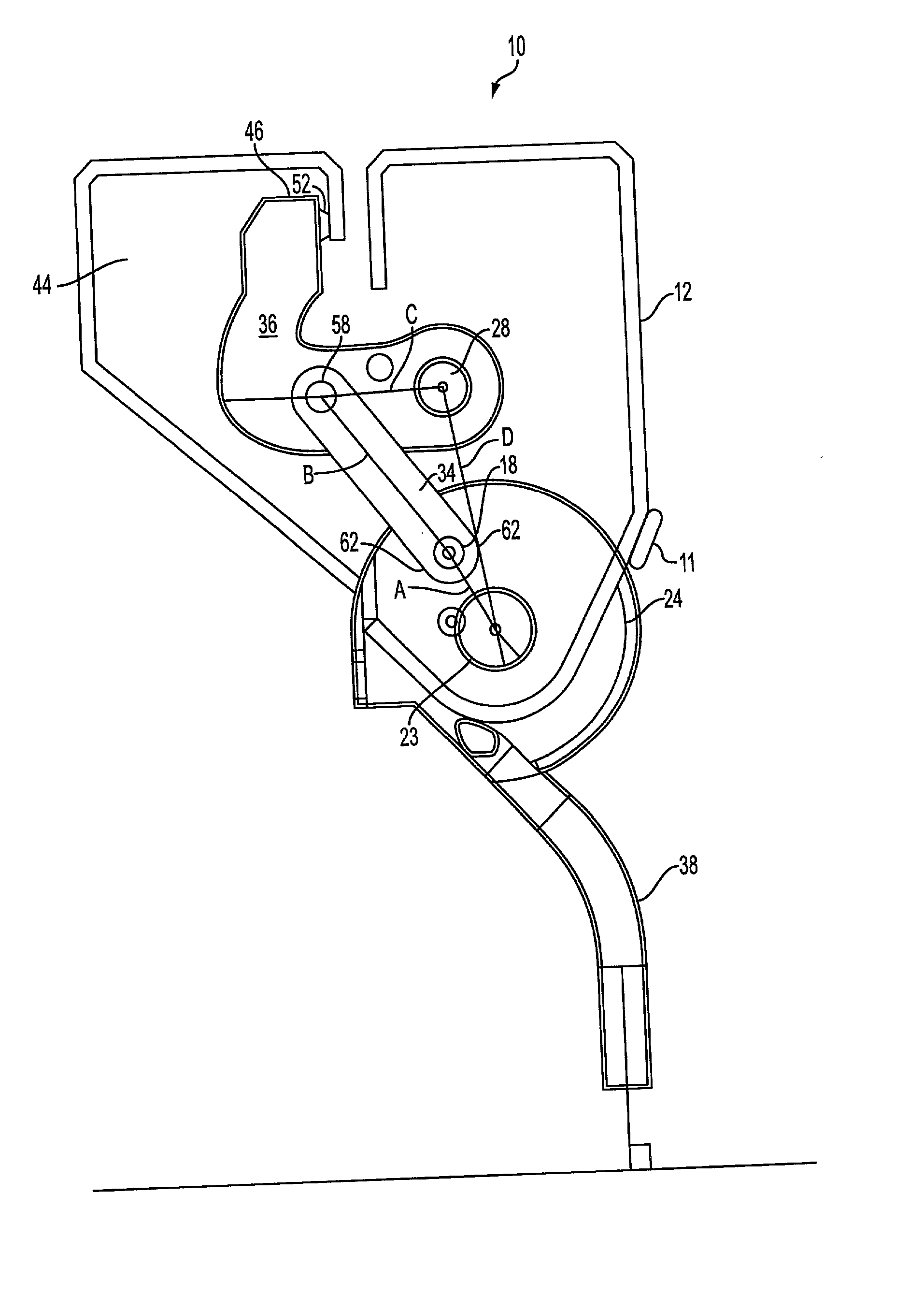
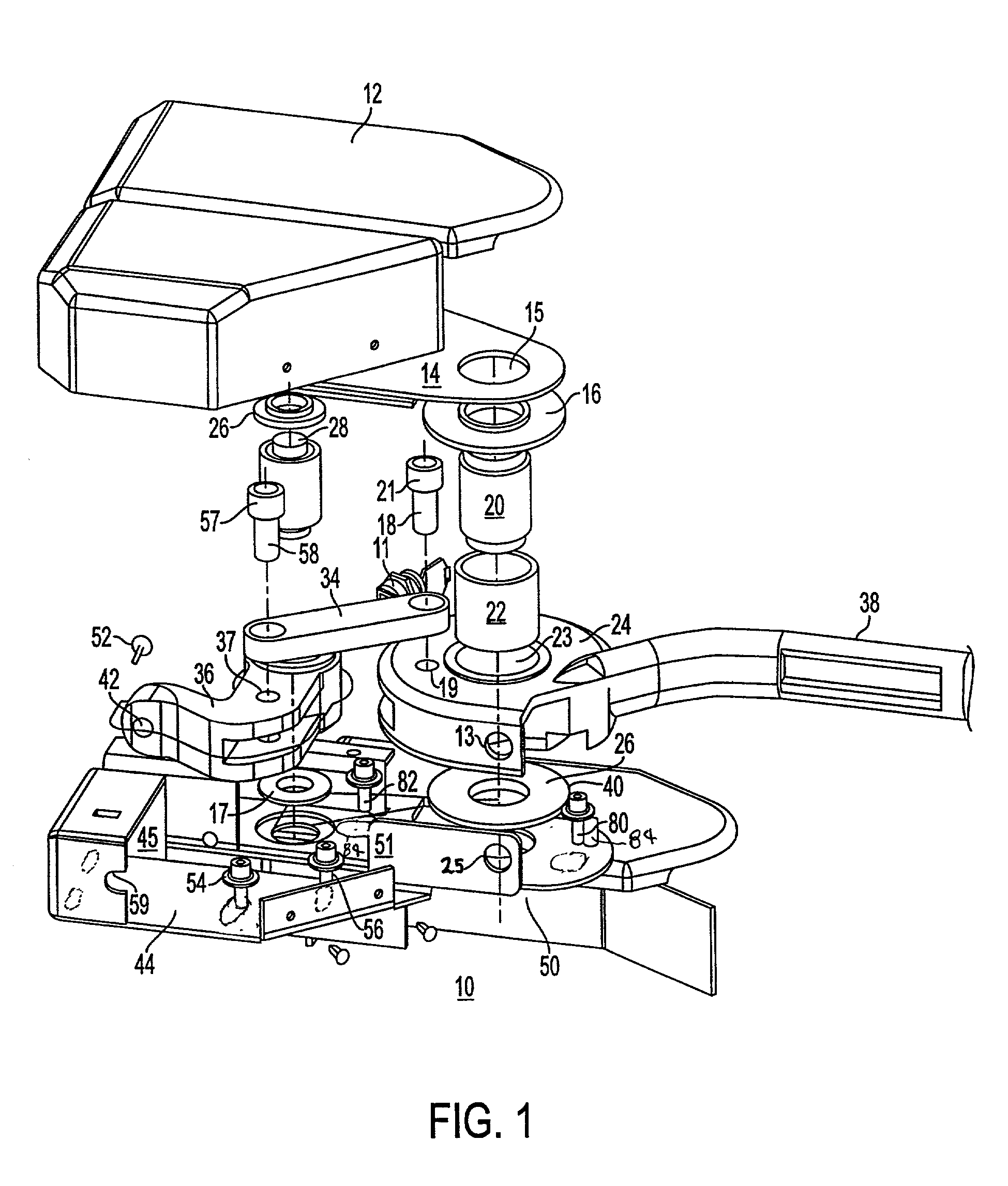
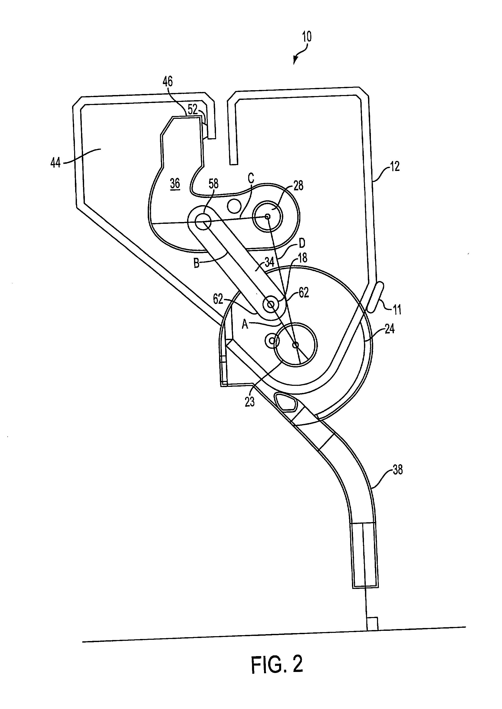
[0023] FIG. 1 illustrates a door latch assembly 10 having a cover plate 12, a catch 36 and a base 50. The cover plate 12 is attached to an outward support 14 via machine screws 60. The pivot pin 20 has a first and second end and the first end is inserted vertically through the structural washer 16 into a circular slot 15 of the outward support 14. The structural washer 16 is spot welded to the outward support 14 to resist contact stress of pivot pin 20. The second end of the pivot pin 20 is inserted through the bushing 22 into the center slot 23 of the driving link 24. The bushing 22 is coupled with the driving link 24 adapting the driving link 24 for receiving and retaining the pivot pin 20 and enabling the driving link 24 to rotate about the pivot pin 20 in a circular motion.

[0024] A handle 38 is integral to the driving link 24. The handle 38 and driving link 24 rotate about the pivot pin 20 with a swing angle of 60 degrees. A force may be exerted onto the handle 38 by a user caus...


PUM


Abstract

The present invention provides a latch device and method for securing a panel such as a door panel to a frame. The latch device has a housing mounted to the door panel with a catch having a contact portion pivotally mounted in the housing for rotation about a first axis while a handle assembly is mounted in the housing for rotation about a second axis. A strike is mounted on the frame such that the strike can receive the catch. The handle assembly is moveable between a first position where the contact portion of the catch is urged into contact against the strike and second position where the catch is retracted from the strike. A link is pivotally mounted to the catch at one point and to the handle assembly at a second point. An adjustment device is provided. The latch device also has a compliance element that absorbs forces resulting from the engagement of the latch assembly.

Description

[0001] This application claims priority of provisional patent application serial No. 60 / 256,547 entitled Door Latch filed Dec. 29, 2000, in the name of Allan D. Kelly, the disclosure of which is hereby incorporated by reference.[0002] The present invention relates generally to latching devices and more particularly to latch assemblies for fastening hinged doors, panels and the like.[0003] Various latches are known, including a number of latch assemblies which are operable for securing two panels or a panel against a corresponding frame. In certain applications such as in the case of doors or panels which need to be sealed when closed, such as for example, refrigerator doors, these latching assemblies are advantageously employed. Generally, latches of this type are mounted proximate to the edges of the first panel and on engagement are adapted to compress the first panel against the corresponding second panel or frame and into a secured position. These assemblies are generally actuat...

Claims


Application Information

Patent Timeline
Patent Type & Authority Applications(United States)
IPC IPC(8): E05B15/00E05B17/00E05B41/00E05B65/00F25D23/02
CPCE05B15/0086E05B17/0025Y10S292/60E05B65/0042F25D23/028E05B41/00Y10T292/0945Y10T292/0946Y10T292/705
Inventor KELLY, ALLAN D.
Owner THERMO ELECTRON A DE
Why Eureka
Try Eureka