Fuel cell actuation mechanism for combustion-powered tool

a fuel cell and actuation mechanism technology, applied in the direction of manufacturing tools, nailing tools, stapling tools, etc., can solve problems such as user fatigue, achieve the effects of reducing the tool actuation force, and facilitating fuel cell movemen

Active Publication Date: 2011-03-03
ILLINOIS TOOL WORKS INC
View PDF18 Cites 4 Cited by
  • Summary
  • Abstract
  • Description
  • Claims
  • Application Information

AI Technical Summary

Benefits of technology

[0006]The above-listed drawback of conventional combustion tools is met or exceeded by the present tool, featuring an actuation mechanism which reduces the tool actuation force. In the preferred embodiment, an actuator is provided which extends from the fuel cell to the valve sleeve a sufficient distance to create a lever action on the fuel cell to facilitate fuel cell movement to the activation or fuel delivery position. By extending the actuator, the movement of the valve sleeve toward the cylinder head to close the combustion chamber creates a greater mechanical advantage over the fuel cell linkage than conventional combustion nailers. In the preferred embodiment, the actuator is extended at least as far as a main tool longitudinal axis.
[0007]More specifically, a combustion nailer includes a tool housing, a combustion source disposed at least partially in the housing and including a valve sleeve reciprocating relative to a cylinder head along a longitudinal tool axis between a rest position and a pre-firing position, a fuel cell chamber defined in the housing in operational proximity to the combustion source and dimensioned for accommodating at least one fuel cell, at least one pivot point associated with the fuel cell chamber and transverse to the tool axis for facilitating movement of the fuel cell between a non-activated position and an activated position, and at least one actuator pivotable about the at least one pivot point and engaging the valve sleeve at a point closer to the tool axis than to the fuel cell chamber such that movement of the valve sleeve from the rest position to the pre-firing position causes movement of the fuel cell from the non-activated position to the activated position.
[0008]In another embodiment, a combustion nailer includes a tool housing, a combustion source disposed in the housing and including a valve sleeve reciprocating relative to a cylinder head along a longitudinal tool axis between a rest position and a pre-firing position. A fuel cell chamber is defined in the housing in operational proximity to the combustion source and is dimensioned for accommodating at least one fuel cell. At least one pivot point is associated with the fuel cell chamber and extending transverse to the tool axis for facilitating movement of the fuel cell between a non-activated position and an activated position. At least one actuator is pivotable about the at least one pivot point and extends from the pivot point at least to the tool axis for engaging the valve sleeve.

Problems solved by technology

The actuation force is sufficient to contribute to user fatigue after periods of extended tool operation.

Method used


Image

  • Fuel cell actuation mechanism for combustion-powered tool
  • Fuel cell actuation mechanism for combustion-powered tool
  • Fuel cell actuation mechanism for combustion-powered tool

Examples


Embodiment Construction

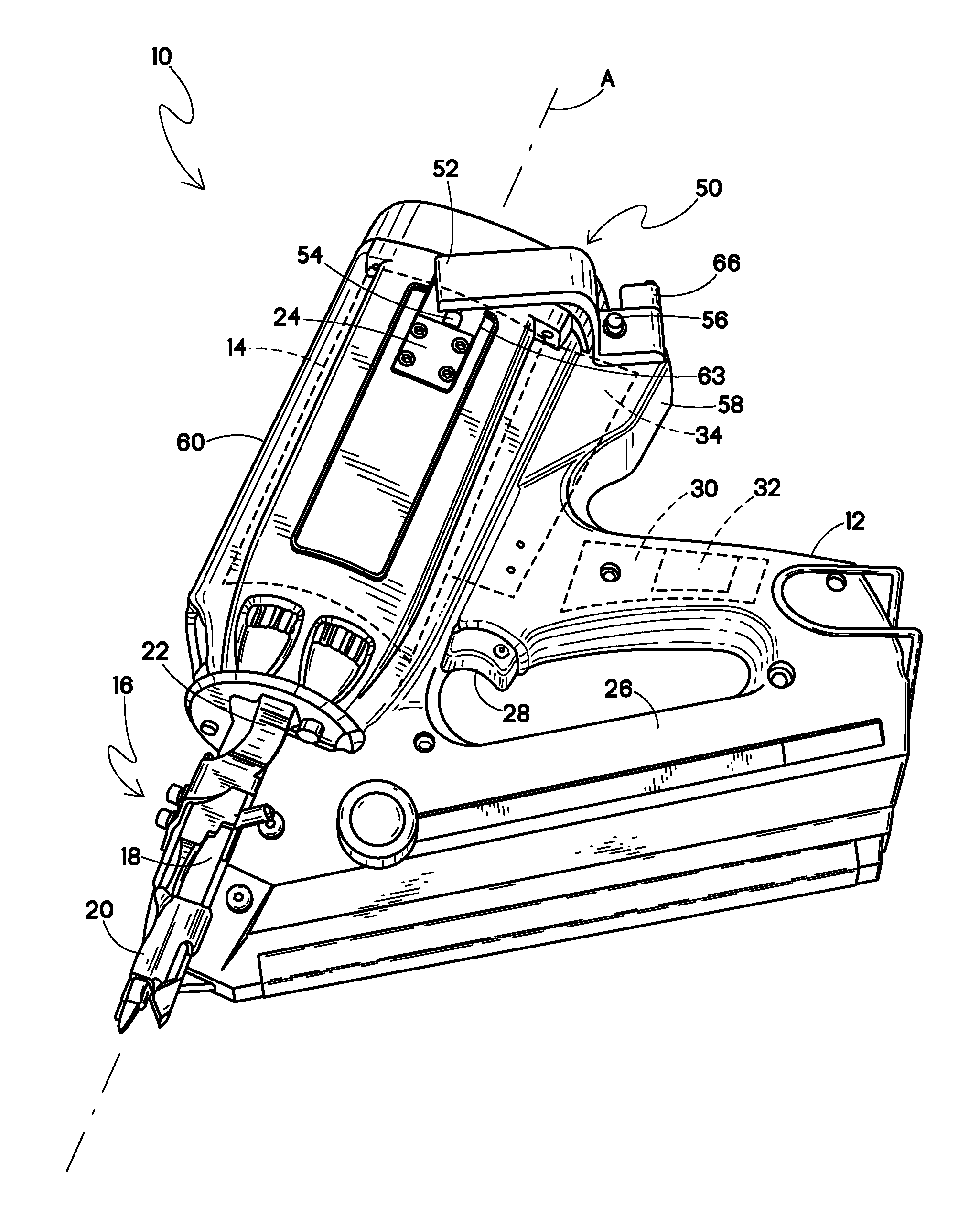
[0022]Referring now to FIG. 1, a combustion-powered, fastener-driving tool suitable for incorporating the present handle housing is generally designated 10. While the tool 10 is depicted as being of the type described in the patents listed above, other types of fastener-driving tools are contemplated as having the potential of incorporation of the present handle housing. Also, the tool 10 is depicted as a framing tool, however so-called trim tools are also considered suitable for use with the present actuation mechanism. The tool 10 includes a main housing 12, usually made of injection molded plastic. A power source 14 (preferably a combustion-powered power source as is known in the art and shown hidden) is at least partially enclosed within the housing 12, which may be provided in one or more components, as is known in the art.

[0023]Other major components of the tool are the nosepiece assembly 16, including a nosepiece 18 typically secured to the power source and configured for rec...


PUM

PropertyMeasurementUnit
movementaaaaaaaaaa
angleaaaaaaaaaa
mechanical advantageaaaaaaaaaa

Abstract

A combustion nailer includes a tool housing, a combustion source disposed at least partially in the housing and including a valve sleeve reciprocating relative to a cylinder head along a tool axis between a rest position and a pre-firing position, a fuel cell chamber in the housing in operational proximity to the combustion source and dimensioned for accommodating a fuel cell, at least one pivot point associated with the fuel cell chamber transverse to the tool axis for facilitating movement of the fuel cell between a non-activated position and an activated position, and at least one actuator pivotable about the pivot point and engaging the valve sleeve at a point closer to the tool axis than to the fuel cell chamber such that movement of the valve sleeve from the rest position to the pre-firing position causes movement of the fuel cell from the non-activated position to the activated position.

Description

BACKGROUND[0001]The present invention relates generally to handheld power tools, and specifically to combustion-powered fastener-driving tools, also referred to as combustion tools or combustion nailers.[0002]Combustion-powered tools are known in the art, and one type of such tools, also known as IMPULSE® brand tools for use in driving fasteners into workpieces, is described in commonly assigned patents to Nikolich U.S. Pat. Re. No. 32,452, and U.S. Pat. Nos. 4,522,162; 4,483,473; 4,483,474; 4,403,722; 5,197,646; 5,263,439 and 6,145,724, all of which are incorporated by reference herein. Similar combustion-powered nail and staple driving tools are available commercially from ITW-Paslode of Vernon Hills, Ill. under the IMPULSE®, BUILDEX® and PASLODE® brands.[0003]Such tools incorporate a tool housing enclosing a small internal combustion engine. The engine is powered by a canister of pressurized fuel gas, also called a fuel cell. A battery-powered electronic power distribution unit p...

Claims


Application Information

Patent Timeline
Patent Type & Authority Applications(United States)
IPC IPC(8): B25C1/08
CPCB25C1/08
Inventor TAYLOR, WALTER J.WALTHALL, BARRYSCHWARTZENBERGER, J. WESTLEYPURPURA, JAMES A.
Owner ILLINOIS TOOL WORKS INC
Why Eureka
Try Eureka