
Side loading low force clutch lever for motorcycles

a clutch lever and side-loading technology, applied in the field of clutch levers, can solve the problems of exceed the maximum load, and difficult to fit the clutch lever head through the slot, so as to achieve less tension force, easy to attach and detach, and less travel distance of the clutch cable

Active Publication Date: 2021-05-04
ZAEHNLE ARTHUR
View PDF4 Cites 0 Cited by
  • Summary
  • Abstract
  • Description
  • Claims
  • Application Information

AI Technical Summary

Benefits of technology

This patent describes a modified clutch lever and mounting bracket that allows for easy adjustment and replacement of the clutch lever. The design also allows for very small input forces, making it easier to shift gears. The clutch cable attachment design facilitates easy loading and unloading of the cable, with a side loading arrangement that allows for secure attachment. The invention also includes a cover that has a slit for the clutch cable to pass through, and a slot in the mounting bracket for easy adjustment of the clutch lever. Overall, this invention simplifies the process of installing and modifying a clutch lever on a motorcycle.

Problems solved by technology

It can be difficult to fit the head of the clutch lever through this slot and into this recess, due to the high forces of tension required to get needed slack in the clutch cable.
This can be especially difficult if the clutch is designed to require a low amount of travel in the clutch cable, which can correspond with a short offset distance between the pivot hole and where the clutch cable attaches to the clutch lever.
If the clutch lever is made of aluminum or other relatively weak materials, the geometry can be insufficient for the design and a maximum load can be exceeded, causing the clutch lever to exceed its strength limit when in use and fail, at least partially.

Method used


Image

  • Side loading low force clutch lever for motorcycles
  • Side loading low force clutch lever for motorcycles
  • Side loading low force clutch lever for motorcycles

Examples


Embodiment Construction

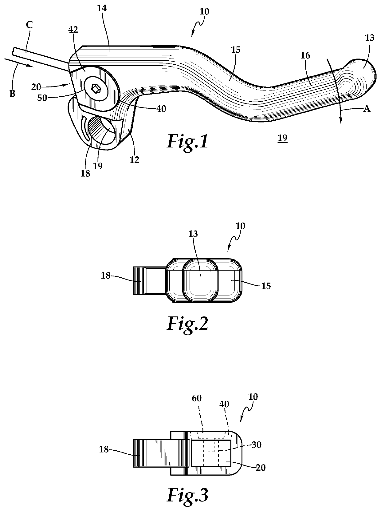
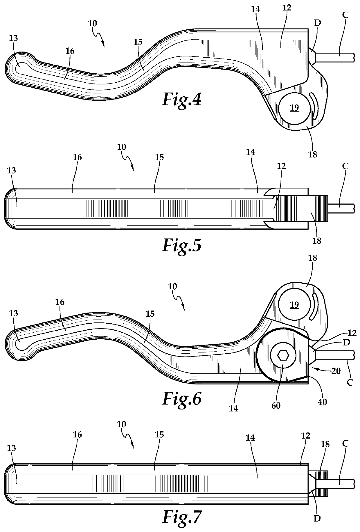
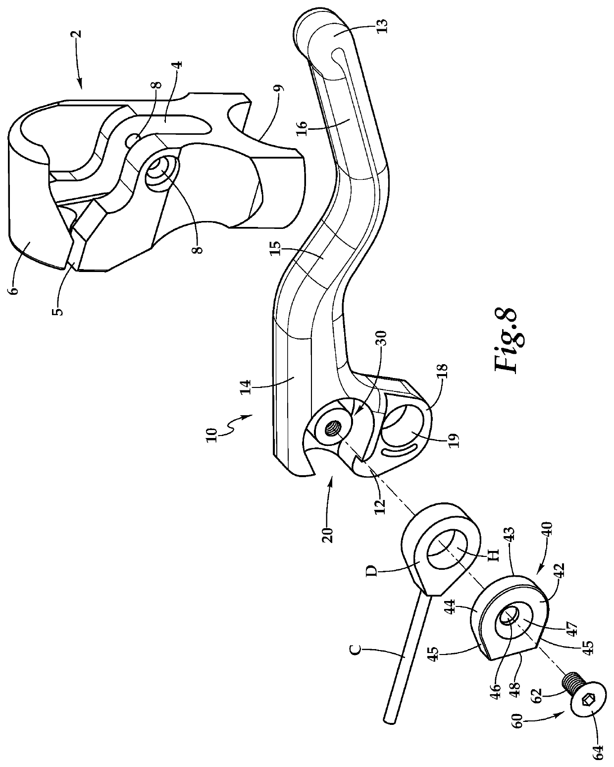
[0042]Referring to the drawings, wherein like reference numerals represent like parts throughout the various drawing figures, reference numeral 10 is directed to a clutch lever (FIGS. 1-10) which is pivotably supported by a mounting bracket (FIG. 8) attached to a motorcycle. The clutch lever 10 is configured to securely support a clutch cable C, and particularly a head D of the cable C with a hole H in the head D supported upon a post 30 within an anchor recess 20 of the clutch lever 10. Secure and easy clutch actuation and clutch assembly / disassembly is thus facilitated.

[0043]With particular reference to FIGS. 8 and 9, basic details of the clutch lever 10 and associated structures are described, according to one exemplary embodiment. The clutch lever 10 includes a proximal end 12 opposite a distal end 13. The proximal end 12 includes a collar 18 surrounding a pivot hole 19 which provides one portion of a pivot, along with pivot pin holes 8 supporting a pivot pin within the mounting...


PUM


Abstract

The clutch lever includes a pivot at a proximal end which pivots relative to a mounting bracket and has an arm extending distally from the proximal end. An anchor recess is provided adjacent to the pivot at the proximal end. A post extends from an inner wall of the anchor recess. A clutch cable with a head at a distal end, and with a hole in the head, can fit within the anchor recess with the post passing through the hole in the head. The post and sidewalls thus support the clutch cable relative to the clutch lever. A cap encloses the anchor recess with a depression on an inner face thereof, sized to receive and support a tip of the post therein. The post is thus securely supported at both a base and a tip of the post.

Description

CROSS-REFERENCE TO RELATED APPLICATIONS[0001]This application claims benefit under Title 35, United States Code § 119(e) of U.S. Provisional Application No. 62 / 767,723 filed on Nov. 15, 2018.FIELD OF THE INVENTION[0002]The following invention relates to clutch levers for actuating a clutch on a motorcycle. More particularly, this invention relates to clutch levers which are easy to toggle, even on motorcycles which require a large amount of tension force to be applied to move a clutch cable thereof, and which securely support the clutch cable relative to the clutch lever, especially when the clutch lever provides a large mechanical advantage to assist a rider in actuating the clutch lever.BACKGROUND OF THE INVENTION[0003]Clutch levers on motorcycles are a common element which has a somewhat standardized function between most motorcycle makes and models, so that motorcycle riders can have an at least somewhat familiar experience when riding a motorcycle type for the first time. The c...

Claims


Application Information

Patent Timeline
Patent Type & Authority Patents(United States)
IPC IPC(8): B62K23/06B62M25/04G05G1/04
CPCB62K23/06B62M25/04G05G1/04
Inventor ZAEHNLE, ARTHUR
Owner ZAEHNLE ARTHUR
Learn More