Eureka AIR delivers breakthrough ideas for toughest innovation challenges, trusted by R&D personnel around the world.

Remote device and remote device system

a remote device and remote control technology, applied in the field of remote devices and remote control systems, can solve the problems that the light received through a single aperture may not be able to ensure a distance, and achieve the effect of improving the light-reception sensitivity of optical remote controls

Active Publication Date: 2018-08-16
SONY CORP
View PDF2 Cites 0 Cited by
  • Summary
  • Abstract
  • Description
  • Claims
  • Application Information

AI Technical Summary

Benefits of technology

The patent is about a new system that improves the sensitivity of optical remote controls by using a light guide to direct the signal light from the front of an object to a receiver inside the object. This allows for better control of the object from a distance.

Problems solved by technology

However, it is likely that the structure that receives light through a single aperture may not be able to ensure a distance and an angular range in each of which a signal is detectable for each of a plurality of signal frequency bands.

Method used


Image

  • Remote device and remote device system
  • Remote device and remote device system
  • Remote device and remote device system

Examples


first embodiment (a remote device that includes a reflecting structure as a light guiding section) (figs.1 to 20)

1. First embodiment (a remote device that includes a reflecting structure as a light guiding section) (FIGS. 1 to 20)

[0039]1. 1 Outline of remote device system

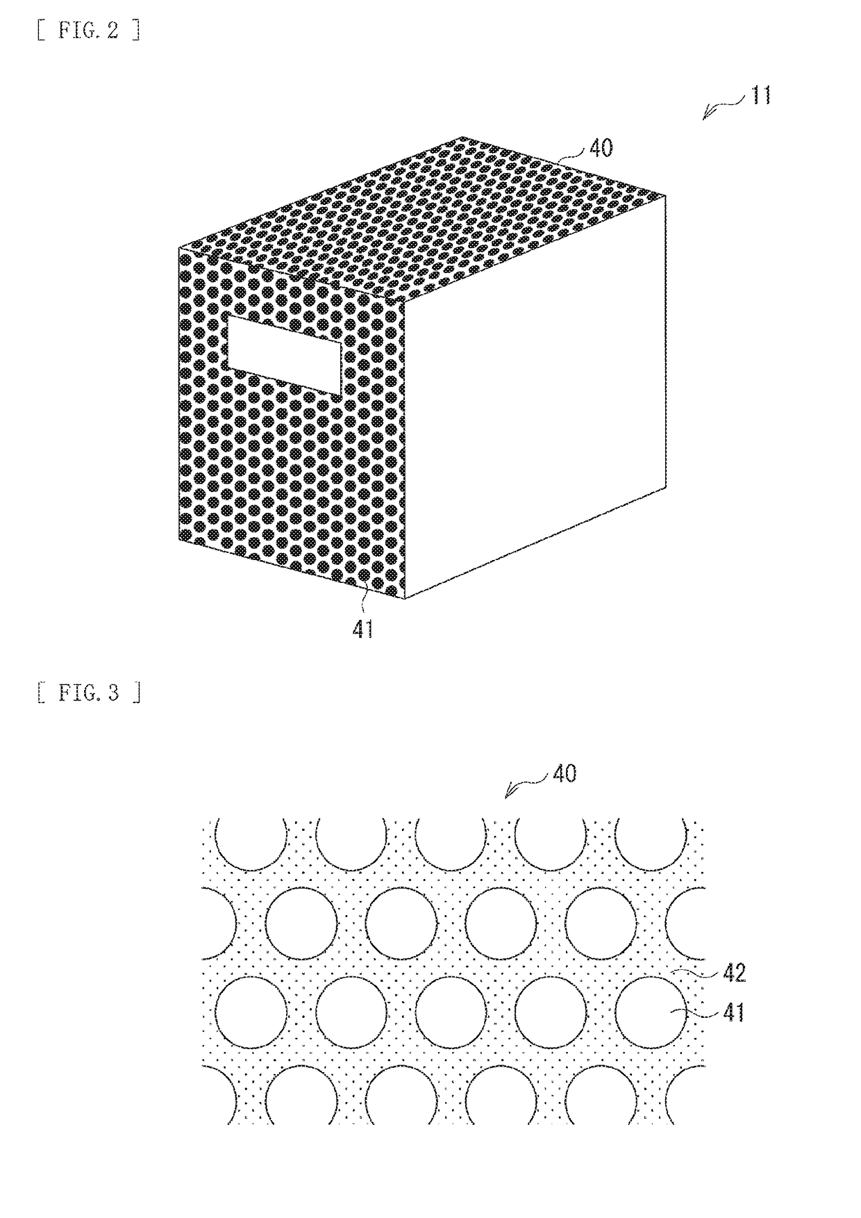
[0040]1. 2 Exterior and inner configuration examples of remote device

[0041]1. 3 Effects

second embodiment (a remote device that includes an on-axis optical member and a wide-angle optical member as a light guiding section) (figs.21 to 26)

2. Second embodiment (a remote device that includes an on-axis optical member and a wide-angle optical member as a light guiding section) (FIGS. 21 to 26)

3. Other embodiments

first embodiment

1. First Embodiment

1. 1 Outline of Remote Device System

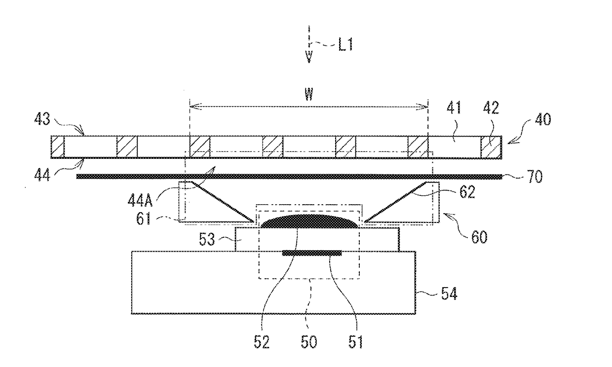
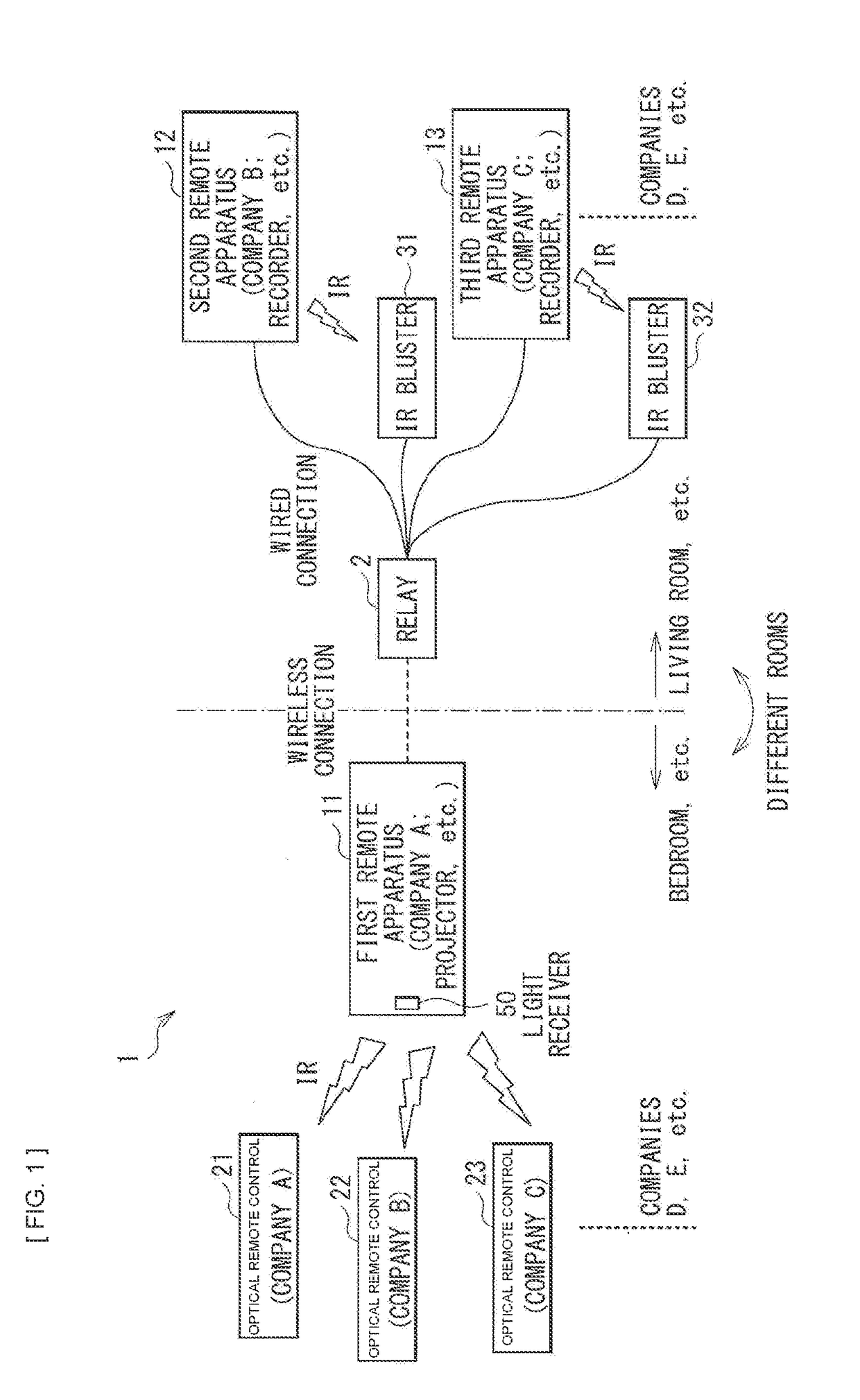
[0042]An optical remote device system includes: an optical remote control; and a device main body that is operable with this optical remote control. The optical remote control is provided with a light emitting body that emits infrared rays as signal light. The device main body is provided with a light receiver having a light receiving sensor that receives the signal light.

[0043]Pieces of carrier light to be emitted are modulated, so that remote control signals are assigned to respective optical remote controls. In general, company products employ different carrier frequencies, as an example listed below.

[0044]Company A: 38 kHz

[0045]Company B: 40 kHz

[0046]Company C: 36 kHz

[0047]Company D: 30 kHz

[0048]A typical product includes a product-dedicated optical remote control and a product-dedicated light receiving sensor. The optical remote control and the light receiving sensor employ a one-to-one configuration. Thus, the light receiv...


PUM


Abstract

A remote device of the disclosure includes: an exterior having a plurality of holes through which light passes, and having a structure in which a surrounding part of the holes blocks the light; a light receiver that is disposed inside the exterior, and receives signal light of one or more optical remote controls; and a light guiding section that is provided between the light receiver and a front surface of the exterior, and guides, to the light receiver, the signal light that has entered a predetermined region of the exterior. The predetermined region includes two or more of the holes.

Description

TECHNICAL FIELD[0001]The disclosure relates to a remote device and a remote device system that are both operable with optical remote controls (remote controller).BACKGROUND ART[0002]An optical remote device system using infrared rays includes: an optical remote control; and a device main body that is operable with this remote control. The remote control is provided with a light emitting body that emits infrared rays as signal light. The device main body is provided with a light receiver that receives the signal light. There are cases where the light receiver is provided inside the exterior of the device main body or another structure. As an example, PTL 1 proposes a technique in which a light receiver is provided inside the exterior. As another example, PTL 2 proposes a technique in which a light receiver is provided inside a speaker grille with punched holes.CITATION LISTPatent Literature[0003][PTL 1] Japanese Unexamined Patent Application Publication No. 2004-320304[0004][PTL 2] J...

Claims


Application Information

Patent Timeline
Patent Type & Authority Applications(United States)
IPC IPC(8): G08C23/06G08C23/04G02B6/10G02B6/122H04N5/44
CPCG08C23/06G08C23/04G02B6/102G02B6/1228H04N5/4403H04N21/42204H04N21/42222H04B10/114H04B10/67H04Q9/00H04Q2209/40H04N5/00
Inventor KANEDA, KAZUMASA
Owner SONY CORP
Why Eureka
Eureka Blog
Learn More