Eureka AIR delivers breakthrough ideas for toughest innovation challenges, trusted by R&D personnel around the world.

Light-receiving element and display device

A technology of light-receiving components and components, applied in the direction of electrical components, radiation control devices, electric solid devices, etc.

Inactive Publication Date: 2011-06-01
JAPAN DISPLAY INC
View PDF3 Cites 0 Cited by
  • Summary
  • Abstract
  • Description
  • Claims
  • Application Information

AI Technical Summary

Problems solved by technology

[0009] As described above, the prior art has limitations on the increase of the photocurrent generated in the light receiving element, and thus it is difficult to sufficiently improve the light receiving sensitivity

Method used


Image

  • Light-receiving element and display device
  • Light-receiving element and display device
  • Light-receiving element and display device

Examples


Embodiment Construction

[0047] Embodiments of the present invention will be described in detail below with reference to the accompanying drawings.

[0048] Structural Example of Light Receiving Element

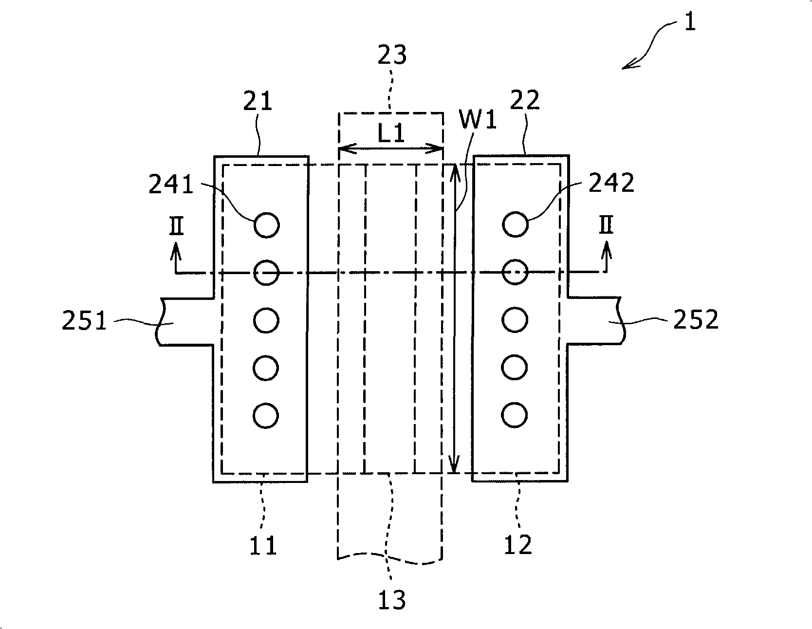
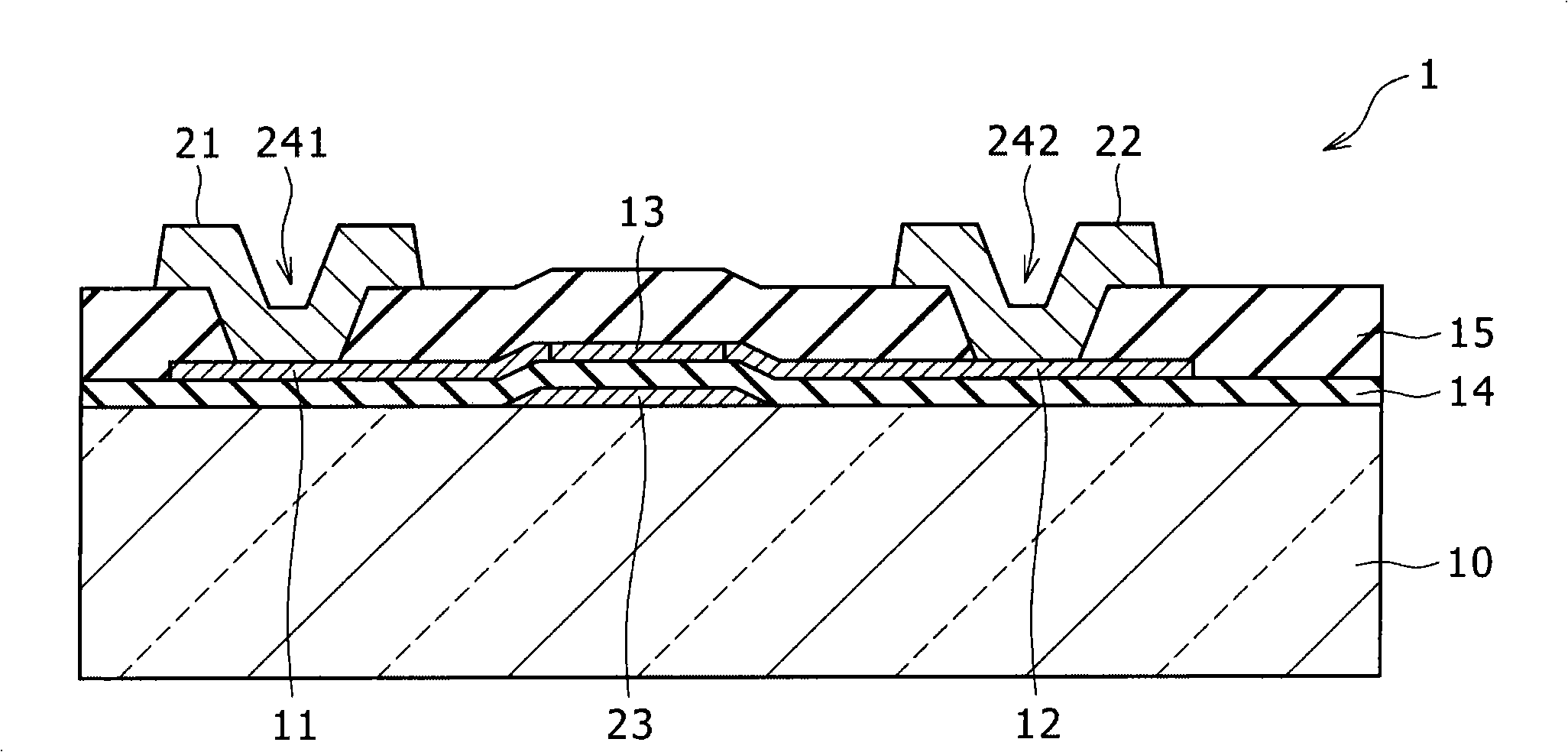
[0049] figure 1 The planar structure of the light receiving element (light receiving element 1 ) of the embodiment of the present invention is shown. figure 2 shows along the figure 1 The cross-sectional structure of the light receiving element 1 along the middle line II-II.

[0050] The light receiving element 1 is a light sensor having a so-called PIN photodiode. The light receiving element 1 has: a glass substrate 10; a p+ layer 11 provided on one surface side of the glass substrate 10 as a first conductivity type semiconductor region; n+ layer 12 of a type semiconductor region; and a light receiving portion 13 provided between the p+ layer 11 and n+ layer 12 as an intermediate semiconductor region. The p + layer 11 is electrically connected to the anode electrode 21 through the contact po...


PUM


Abstract

A light-receiving element includes: a first-conductivity-type semiconductor region configured to be formed over an element formation surface; a second-conductivity-type semiconductor region configured to be formed over the element formation surface; an intermediate semiconductor region configured to be formed over the element formation surface between the first-conductivity-type semiconductor region and the second-conductivity-type semiconductor region, and have an impurity concentration lower than impurity concentrations of the first-conductivity-type semiconductor region and the second-conductivity-type semiconductor region. The light-receiving element further includes: a first electrode configured to be electrically connected to the first-conductivity-type semiconductor region; a second electrode configured to be electrically connected to the second-conductivity-type semiconductor region; and a control electrode configured to be formed in an opposed area that exists on the element formation surface.

Description

[0001] Cross References to Related Applications [0002] The present invention contains subject matter related to Japanese Patent Application JP2008-228255 filed with Japan Patent Office on September 5, 2008 and Japanese Patent Application JP 2007-332100 filed with Japan Patent Office on December 25, 2007, both of which are herein The entire contents of the Japanese patent application are incorporated herein by reference. technical field [0003] The present invention relates to a light receiving element having a control electrode and a display device including such a light receiving element. Background technique [0004] In recent years, in display devices such as liquid crystal display devices and organic electroluminescent (EL) display devices, light receiving elements such as photodiodes are widely used to detect and control the brightness and contrast of displayed images. The photodiode is arranged in a display device together with a display element having a drive circ...

Claims


Application Information

Patent Timeline
Patent Type & Authority Patents(China)
IPC IPC(8): H01L31/105H01L27/144H01L27/32
Inventor 大谷夏树田中勉国井正文池田雅延伊藤良一
Owner JAPAN DISPLAY INC
Why Eureka
Eureka Blog
Learn More