Efficient micro fuel cell systems and methods

a fuel cell and micro-chip technology, applied in the field of fuel cell technology, can solve the problems of burdensome storage and transportation of liquid hydrogen, low energy density of gaseous hydrogen, and low practicality of portable fuel, and achieve the effect of facilitating heat production and reducing the amount of moistur

Active Publication Date: 2005-01-13
ULTRACELL LLC
View PDF87 Cites 90 Cited by
  • Summary
  • Abstract
  • Description
  • Claims
  • Application Information

AI Technical Summary

Benefits of technology

[0009] Methods for shutting down a fuel cell system are also described that reduce the amount of moisture and gases in the reformer and in one or more fuel cell components at shut down.
[0010] One hydrogen efficient fuel cell system described here

Problems solved by technology

Gaseous hydrogen has a low energy density that reduces its practicality as a portable fuel.
Liquid hydrogen, which has a suitable energy density, must be stored at extremely low temperatures and high pressures, m

Method used


Image

  • Efficient micro fuel cell systems and methods
  • Efficient micro fuel cell systems and methods
  • Efficient micro fuel cell systems and methods

Examples


Embodiment Construction

[0041] The present invention is described in detail with reference to a few preferred embodiments as illustrated in the accompanying drawings. In the following description, numerous specific details are set forth in order to provide a thorough understanding of the present invention. It will be apparent, however, to one skilled in the art, that the present invention may be practiced without some or all of these specific details. In other instances, well known process steps and / or structures have not been described in detail in order to not unnecessarily obscure the present invention.

[0042] 1. Fuel Cell System

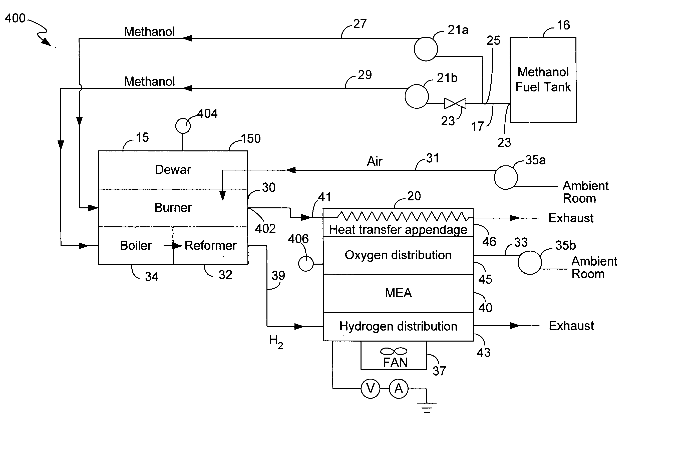
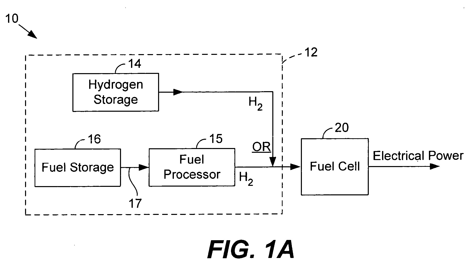
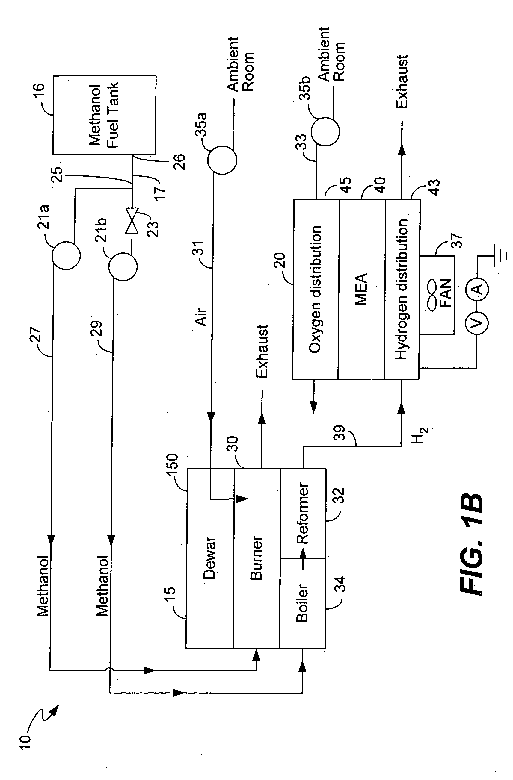
[0043]FIG. 1A illustrates a fuel cell system 10 for producing electrical energy in accordance with one embodiment of the present invention. Fuel cell system 10 comprises a hydrogen fuel supply 12 and a fuel cell 20.

[0044] Hydrogen supply 12 provides hydrogen to fuel cell 20. As shown, supply 12 includes a ‘reformed’ hydrogen supply that processes a fuel source to produce hydro...


PUM

PropertyMeasurementUnit
Temperatureaaaaaaaaaa
Poweraaaaaaaaaa

Abstract

Described herein are fuel cell systems and methods of using fuel cell systems. The systems include a fuel cell that generates electrical energy using hydrogen and a fuel processor that produces hydrogen from a fuel source. The fuel processor includes a reformer and a burner that heats the reformer. One heat efficient fuel cell system described herein heats internal portions of a fuel cell using a heating medium from a fuel processor. The heating medium may comprise gases exhausted at high temperatures from the fuel processor, which are then transported to the fuel cell. The heating medium may also include a gas that reacts catalytically in the fuel cell to produce heat. Systems and methods for expediting fuel cell system start up are provided. Methods for shutting down a fuel cell system are also described that reduce the amount of moisture and gases in the reformer and in one or more fuel cell components. One hydrogen efficient fuel cell system described herein transports hydrogen to an inlet of a burner. The hydrogen may comprise unused hydrogen from a fuel cell and/or hydrogen produced in a reformer. The burner comprises a catalyst that facilitates production of heat in the presence of the hydrogen.

Description

CROSS-REFERENCE TO RELATED APPLICATIONS [0001] This application claims priority under 35 U.S.C. §119(e) from co-pending U.S. Provisional Patent Application No. 60 / 482,996 entitled “Fuel cell system startup procedure and self-heating apparatus”, which is incorporated by reference for all purposes; this application also claims priority under 35 U.S.C. §119(e) from co-pending U.S. Provisional Patent Application No. 60 / 483,416 entitled “Fuel Preheat in Portable Electronics Powered by Fuel Cells”, which is incorporated by reference for all purposes; and this application additionally claims priority under 35 U.S.C. §119(e) from co-pending U.S. Provisional Patent Application No. 60 / 482,981 entitled “Micro machined fuel stack with integral cooling and humidification”, which is incorporated by reference for all purposesBACKGROUND OF THE INVENTION [0002] The present invention relates to fuel cell technology. In particular, the invention relates to systems for improving fuel cell system effici...

Claims


Application Information

Patent Timeline
IPC IPC(8): B01J19/00B01J19/24C01B3/24C01B3/38C08F4/636C08F4/649C08F4/651C08F4/654H01MH01M8/04H01M8/06H01M8/10
CPCB01J8/0214B01J8/0221B01J8/0242B01J8/0285B01J8/0438B01J8/0484B01J19/0093B01J19/249B01J2208/00061B01J2208/00309B01J2208/00398B01J2208/00407B01J2208/00415B01J2208/00504B01J2208/00646B01J2208/00716B01J2219/00783B01J2219/00835B01J2219/00873B01J2219/00907B01J2219/2453B01J2219/2458B01J2219/2459B01J2219/2462B01J2219/2465B01J2219/2467B01J2219/247B01J2219/2475B01J2219/2479B01J2219/2481B01J2219/2482C01B3/323C01B3/38C01B2203/0233C01B2203/0244C01B2203/0261C01B2203/066C01B2203/0805C01B2203/0811C01B2203/0822C01B2203/0827C01B2203/0844C01B2203/0866C01B2203/1223C01B2203/1247C01B2203/142C01B2203/82H01M8/0228H01M8/0247H01M8/0258H01M8/0267H01M8/04007H01M8/04022H01M8/04037H01M8/04067H01M8/04223H01M8/04268H01M8/04298H01M8/0435H01M8/04365H01M8/04373H01M8/04388H01M8/04425H01M8/04559H01M8/04589H01M8/04604H01M8/04619H01M8/04626H01M8/04731H01M8/04738H01M8/04753H01M8/04768H01M8/04776H01M8/04955H01M8/0618H01M8/0631H01M8/0662H01M2008/1095Y02E60/523Y02E60/50H01M8/04225H01M8/2483Y02P20/10Y02P70/50
Inventor KAYE, IAN W.TUCKER, GERRY
Owner ULTRACELL LLC
Why Eureka
Try Eureka