

Table saw
a table saw and table saw technology, applied in the field of table saws, can solve the problems of hard swinging or vibrating of free bolts, and achieve the effect of improving the precision of cutting and sizing work pieces and hard swinging or vibrating
- Summary
- Abstract
- Description
- Claims
- Application Information
AI Technical Summary
Benefits of technology
Problems solved by technology
Method used
Image

Examples
Embodiment Construction
[0026]Referring now to the drawings where like characteristics and features among the various figures are denoted by like reference characters.
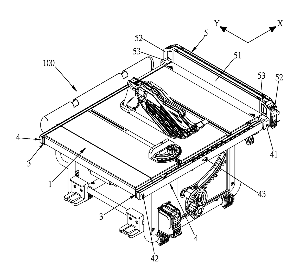
[0027]Please refer to FIGS. 4 to 14, a table saw 100 may comprise a table 1, a saw 2, a track 3, a slide strip 4, and a fence member 5.
[0028]The table 1 may have an axial direction (the arrow X in FIG. 5) and a radial direction (the arrow Y in FIG. 5) which are orthogonal to each other.
[0029]The saw 2 may be arranged at a predetermined position, for example, the predetermined position is a center of the table 1. A cutting direction of the saw 2 and the radial direction of the table 1 are parallel.
[0030]The track 3 may be arranged at each side of the table 1. An axial direction of the track 3 and the axial direction of the table 1 are parallel.
[0031]Please refer to FIGS. 4, 5, 9, and 10, the slide strip 4 may be slidably engaged with the track 3. An outer surface of the slide strip 4 which is opposite to the track 3 has three position parts. T...
PUM
| Property | Measurement | Unit |
|---|---|---|
| size | aaaaa | aaaaa |
| distance | aaaaa | aaaaa |
Abstract
Description
Claims
Application Information