Laser processing machine

a laser processing machine and laser technology, applied in metal-working equipment, welding equipment, manufacturing tools, etc., can solve the problems of increasing the vibration source of the cutting head, and reducing the efficiency of the laser processing machine.

Active Publication Date: 2018-06-26
MURATA MASCH LTD
View PDF46 Cites 0 Cited by
  • Summary
  • Abstract
  • Description
  • Claims
  • Application Information

AI Technical Summary

Benefits of technology

[0008]In view of the foregoing, preferred embodiments of the present invention provide a laser processing machine configured to finely adjust a laser beam irradiated position on a target object to be processed through deflection of a laser beam to significantly reduce or prevent adverse influences on the optical system caused by vibrations of a cutting nozzle.
[0010]According to a preferred embodiment of the present invention, since the optical system head and the nozzle holding head are separately supported by the optical system nozzle support member, it is possible to make vibrations of the cutting nozzle in the nozzle holding head hard to be transmitted to the focusing optical system in the optical system head. Specifically, support may be accomplished through a vibration isolating material. Also, a support structure may be of a type in which the natural frequency increases. Accordingly, adverse influences caused by the focusing optical system on the deflection of the laser beam are significantly reduced or prevented. For this reason, a highly accurate processing is accomplished.
[0012]According to the above described feature, when the processing is to be performed with no cutting gas blown to the target object to be processed, withdrawal of the cutting nozzle to the outside of the processing region is effective to avoid a possible interference brought about by the cutting nozzle.

Problems solved by technology

In the meantime, the processing head referred to above includes a number of component parts, and thus it is relatively heavy.
For this reason, when the processing head as a whole is to be moved, a force of inertia acts enough to make it difficult to accomplish the quick and precise change of direction and quick and precise acceleration or deceleration.
In the laser processing machine, the higher the accelerating or decelerating speed is required in processing, the greater vibration source the cutting head becomes.
Also, even in WO2009 / 146697 A1, in which the movable unit weight is made relatively lightweight, the provision of the optical system and the cutting nozzle in the same processing head results in that vibrations of the cutting nozzle are transmitted to the optical system, thus making it possible for the vibrations of the cutting nozzle to adversely affect the optical system.

Method used


Image

  • Laser processing machine
  • Laser processing machine
  • Laser processing machine

Examples


Embodiment Construction

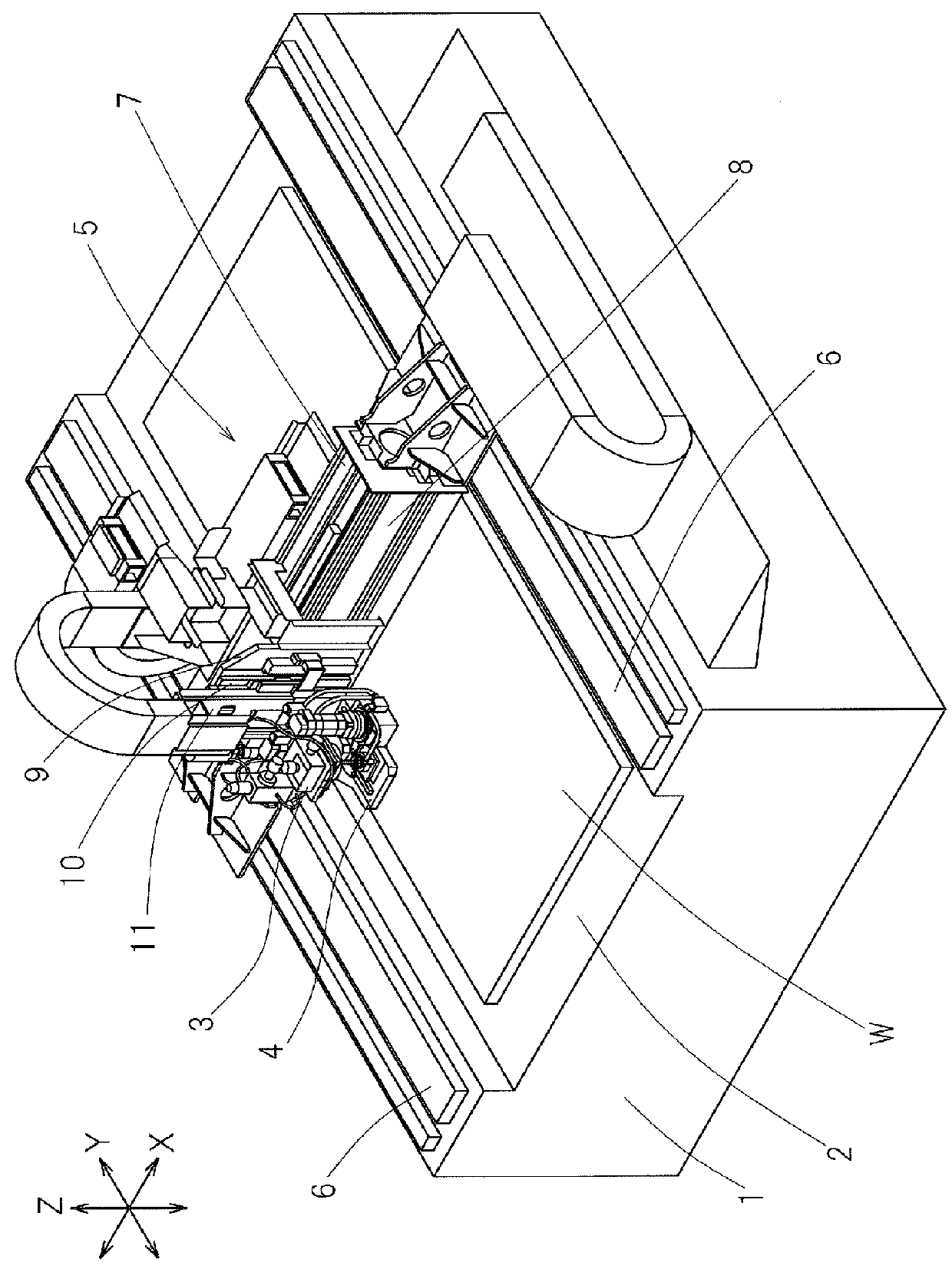
[0026]Preferred embodiments of the present invention will now be described with particular reference to the accompanying drawings. Referring to FIG. 1 which shows an overall perspective view, a laser processing machine according to a preferred embodiment of the present invention includes a bed 1 and a table 2 provided on the bed 1, and a target object W to be processed, prepared from a plate material, is placed on the table 2. The laser processing machine is configured to perform, for example, a cutting process on the target object W to be processed having been placed on the table 2, with an optical system head 3 and a nozzle holding head 4 being moved in three axes directions perpendicular or substantially perpendicular to each other.

[0027]The optical system head 3 and the nozzle holding head 4 are moved by an XYZ axes moving mechanism 5. The XYZ axes moving mechanism 5 includes a Y axis movable body 7, an X axis movable body 9 and a Z axis movable body 11. The Y axis movable body ...


PUM

PropertyMeasurementUnit
thicknessaaaaaaaaaa
thicknessaaaaaaaaaa
forceaaaaaaaaaa

Abstract

An optical system head of the laser processing machine includes a focusing optical system configured to deflect and condense an incident laser beam so that a target object to be processed is irradiated and a deflecting direction adjusting unit configured to adjust the direction of deflection of the laser beams about at least two axes perpendicular or substantially perpendicular to each other. A nozzle holding head of the laser processing machine includes a cutting nozzle configured to blow a cutting gas at a site of the target object, at which the laser beam is irradiated, and a nozzle position adjusting unit configured to adjust the position of the cutting nozzle in a top plane parallel or substantially parallel to the target object. The optical system head and the nozzle holding head are separately supported by an optical system nozzle support member configured to selectively advance or retract in three axis directions relative to the target object.

Description

CROSS REFERENCE TO THE RELATED APPLICATION[0001]This application is based on and claims Convention priority to Japanese patent application No. 2012-029152, filed Feb. 14, 2012, the entire disclosure of which is herein incorporated by reference as a part of this application.BACKGROUND OF THE INVENTION[0002]1. Field of the Invention[0003]The present invention relates to a laser processing machine for cutting a target object to be processed with a laser beam and, more particularly, to a laser processing machine capable of adjusting a laser beam irradiated position on a target object by deflecting such laser beam.[0004]2. Description of the Related Art[0005]The laser processing machine generally includes an optical system such as, for example, a condensing lens, which is operable to condense the incident laser beam and then irradiate a target object to be processed, and a processing head provided with a cutting nozzle for blowing a cutting gas at a portion of the target object where the...

Claims


Application Information

Patent Timeline
Patent Type & Authority Patents(United States)
IPC IPC(8): B23K26/00B23K26/08B23K26/14B23K26/38B23K26/082B23K26/142
CPCB23K26/08B23K26/082B23K26/38B23K26/14B23K26/142B23K26/0876
Inventor OKADA, TAKUYA
Owner MURATA MASCH LTD
Why Eureka
Try Eureka