Method of manufacturing, and a collimator mandrel having variable attenuation characteristics for a CT system

a manufacturing method and collimator technology, applied in the field of computed tomography (ct) diagnostic imaging systems, can solve the problems of patient radiation dose, degrading image quality, tightening of collimator, etc., and achieve the effect of repeatable and precise process

Active Publication Date: 2006-04-18
GENERAL ELECTRIC CO
View PDF12 Cites 66 Cited by
  • Summary
  • Abstract
  • Description
  • Claims
  • Application Information

AI Technical Summary

Benefits of technology

[0009]The present invention is a directed to a manufacturing process overcoming the aforementioned drawbacks. The present invention provides a repeatable and precise process of constructing a collimator mandrel for a CT system. A rod of rigid material is positioned within a cast. The cast defines a void circumferentially around the rod which serves as a layout or pattern for an attenuating layer of epoxy, resin, or other material. Epoxy or other material is then deposited within the void and is allowed to cure. After curing, the cast is removed, and a complexly shaped collimator mandrel results. Alternatively, a thin layer of variable thickness may be deposited or sputtered directly on the outer surface of the rod to provide the complex shape desired.

Problems solved by technology

However, as the detector size increases in the z-axis, the constraints on the collimator tighten.
Increased x-ray coverage increases patient radiation dose and degrades image quality due to the increased scatter in the reconstructed image.
The rigidity of the tungsten, however, makes machining of a solid tungsten rod to have a complex shape difficult and time consuming.
Moreover, machining with a precision required for a CT collimator can be difficult thereby compromising system performance.

Method used


Image

  • Method of manufacturing, and a collimator mandrel having variable attenuation characteristics for a CT system
  • Method of manufacturing, and a collimator mandrel having variable attenuation characteristics for a CT system
  • Method of manufacturing, and a collimator mandrel having variable attenuation characteristics for a CT system

Examples


Embodiment Construction

[0024]The present invention will be described with respect to the blockage, detection, and conversion of x-rays. However, one skilled in the art will appreciate that the present invention is equally applicable for the detection and conversion of other high frequency electromagnetic energy. The present invention will be described with respect to a “third generation” CT scanner, but is equally applicable with other CT systems.

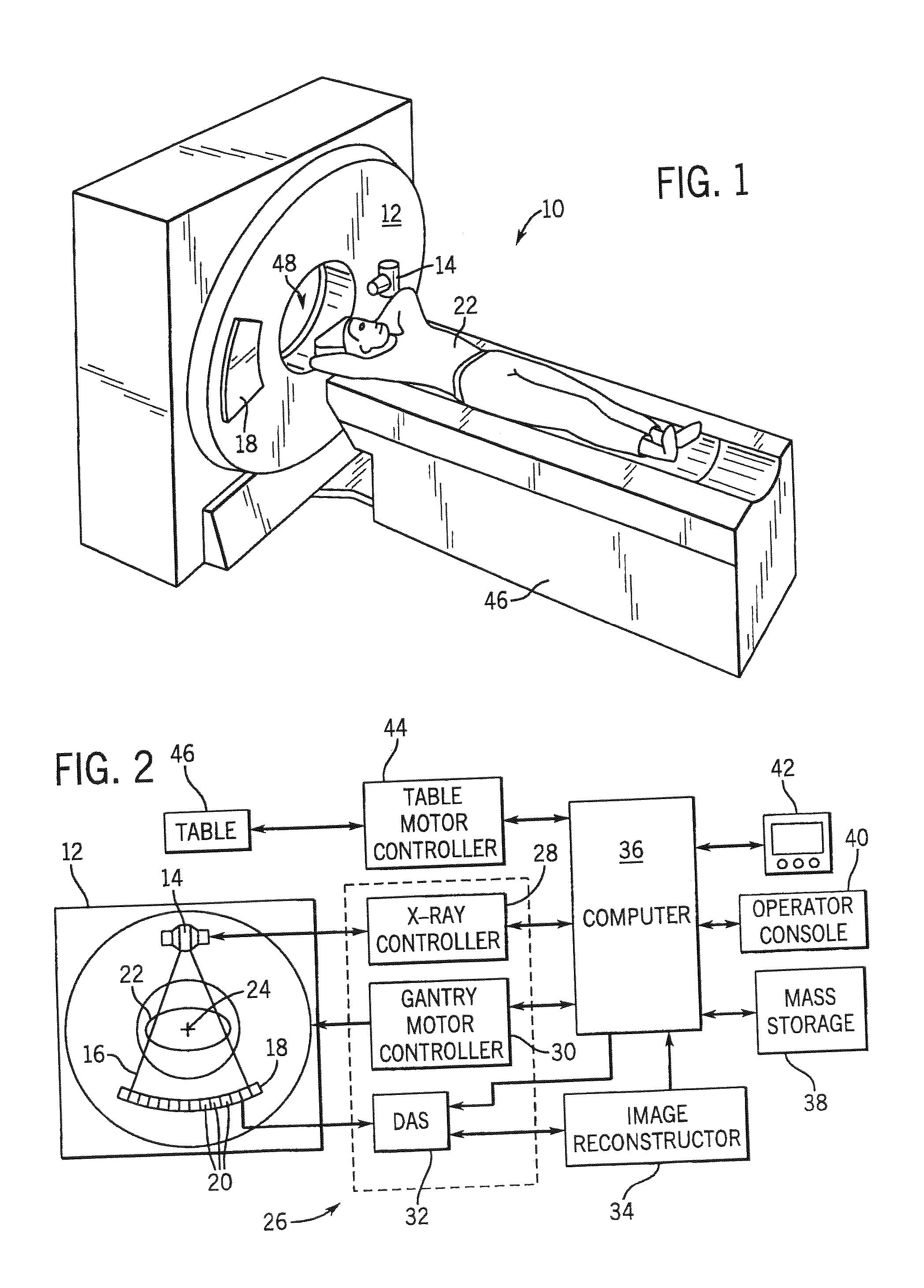
[0025]Referring to FIGS. 1 and 2, a computed tomography (CT) imaging system 10 is shown as including a gantry 12 representative of a “third generation” CT scanner. Gantry 12 has an x-ray source 14 that projects a beam of x-rays 16 toward a detector array 18 on the opposite side of the gantry 12. Detector array 18 is formed by a plurality of detectors 20 which together sense the projected x-rays that pass through a medical patient 22. Each detector 20 produces an electrical signal that represents the intensity of an impinging x-ray beam and hence the attenuated be...


PUM

PropertyMeasurementUnit
thicknessaaaaaaaaaa
CTaaaaaaaaaa
lengthaaaaaaaaaa

Abstract

A method of manufacturing a collimator mandrel having variable attenuation characteristics is presented. The manufacturing process includes the placement of a layer of attenuating material on a core of base material. The layer of attenuating material is relatively thin and varies in thickness circumferentially around the core. The collimator mandrel may be manufactured by placing a cast about a core of non-attenuating material, filling a void between the cast and the core with an attenuating material, allowing the material to cure, and removing the cast from the assembly.

Description

BACKGROUND OF INVENTION[0001]The present invention relates generally to computed tomography (CT) diagnostic imaging systems and, more particularly, to a method of manufacturing a collimator mandrel having variable attenuation characteristics.[0002]Typically, in CT imaging systems, an x-ray source emits a fan-shaped beam toward a subject or object, such as a patient or a piece of luggage. Hereinafter, the terms “subject” and “object” shall include anything capable of being imaged. The beam, after being attenuated by the subject, impinges upon an array of radiation detectors. The intensity of the attenuated beam radiation received at the detector array is typically dependent upon the attenuation of the x-ray beam by the subject. Each detector element of the detector array produces a separate electrical signal indicative of the attenuated beam received by each detector element. The electrical signals are transmitted to a data processing system for analysis which ultimately produces an ...

Claims


Application Information

Patent Timeline
Patent Type & Authority Patents(United States)
IPC IPC(8): G21K5/04
CPCG21K1/04G21K1/02
Inventor SAUNDERS, ROWLANDROSS, STEVENTOTH, THOMAS
Owner GENERAL ELECTRIC CO
Why Eureka
Try Eureka