Laser light source, method of laser oscillation, and method of laser processing

a laser light source and laser technology, applied in the direction of multiplex communication, wavelength-division multiplex system, semiconductor laser, etc., can solve the problems of inability to perform processing a processing object with precision, no degree of freedom in regard to the above point, etc., and achieve the effect of stable operation of the laser light sour

Inactive Publication Date: 2006-11-16
SUMITOMO ELECTRIC IND LTD
View PDF6 Cites 66 Cited by
  • Summary
  • Abstract
  • Description
  • Claims
  • Application Information

AI Technical Summary

Benefits of technology

[0013] The light source section of the laser light source according to the present invention preferably includes a mode-locked fiber laser light source. In this case, each of the first wavelength and the second wavelength becomes stable, and accordingly, the operation of the laser light source becomes stable.

Problems solved by technology

However, in the conventional laser light sources including the ones described in the above two papers, there has been no degree of freedom in regard to the above point.
Owing to this, in laser processing using the conventional laser light sources, there may be the case that processing a processing object with precision cannot be performed.

Method used


Image

  • Laser light source, method of laser oscillation, and method of laser processing
  • Laser light source, method of laser oscillation, and method of laser processing
  • Laser light source, method of laser oscillation, and method of laser processing

Examples


Embodiment Construction

[0030] Hereinafter, the preferred embodiments of the present invention will be described in detail referring to the attached drawings. In the description of the drawings, like reference numerals are attached to like elements, and duplicated descriptions thereof are omitted.

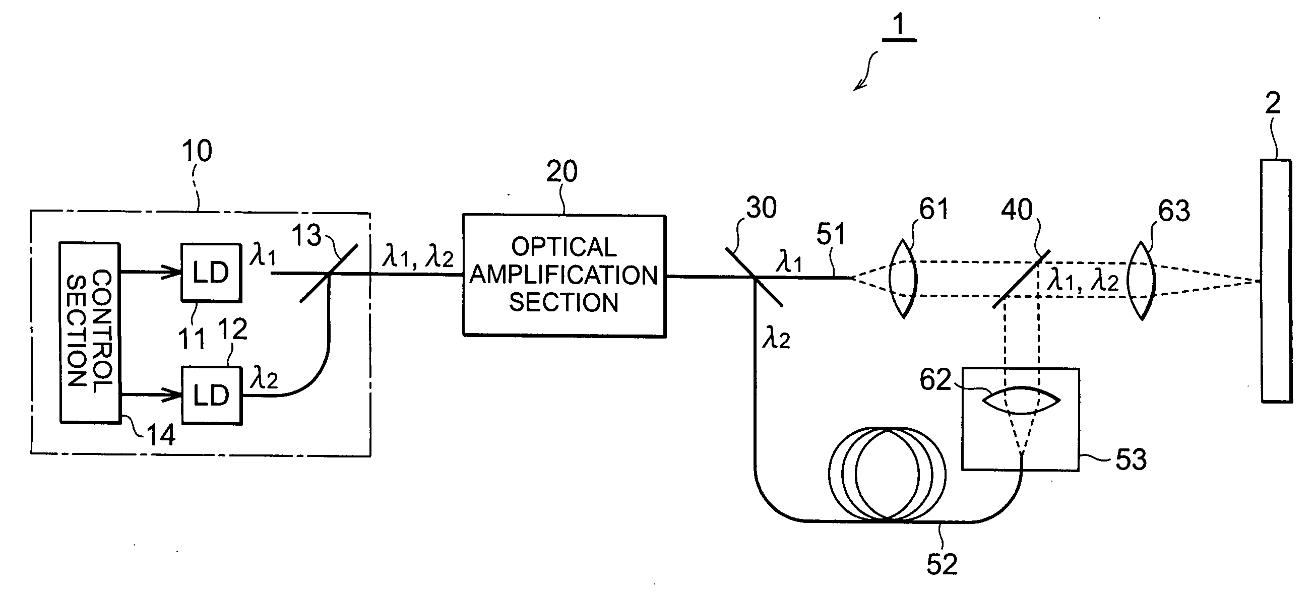
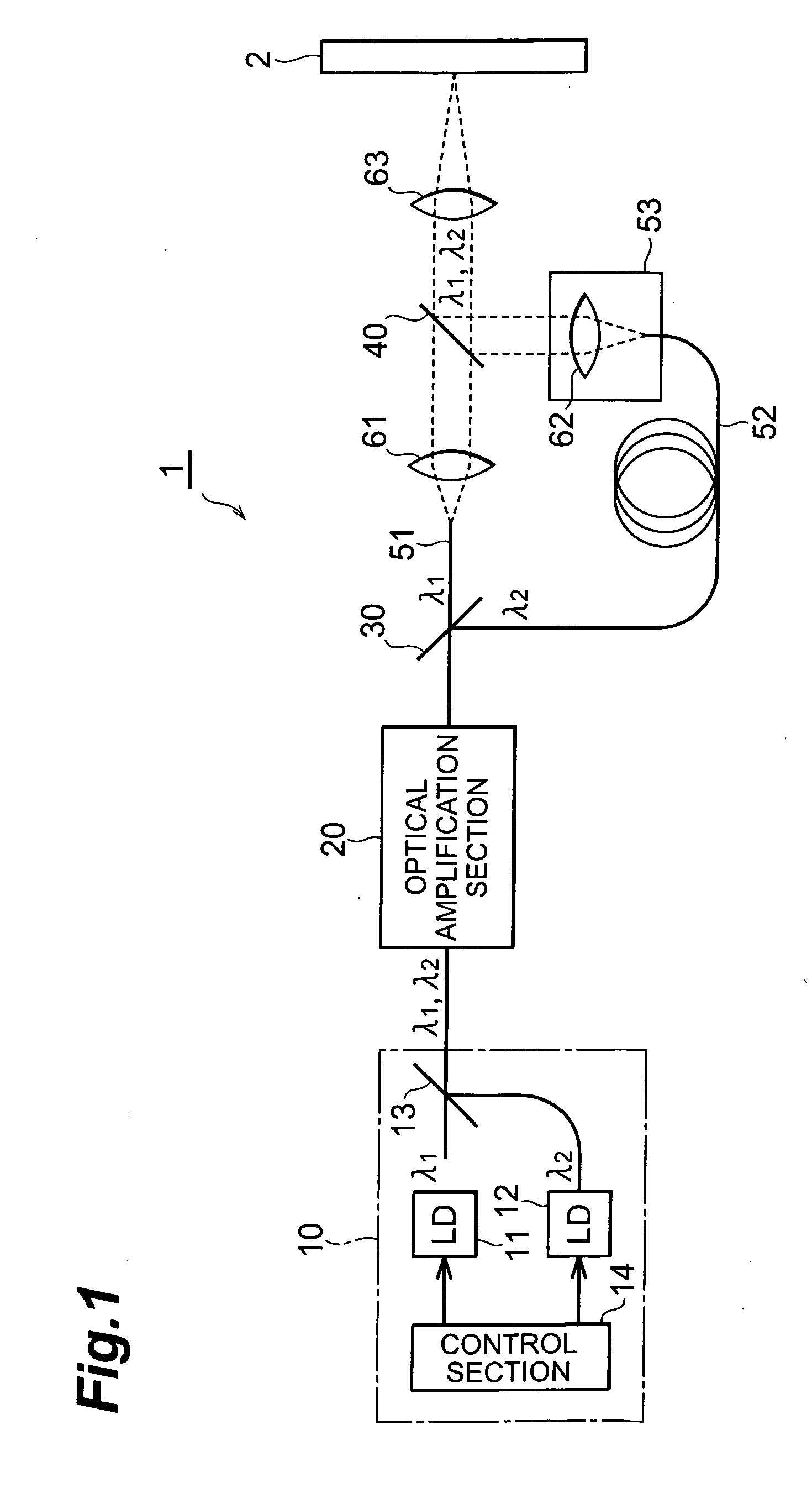
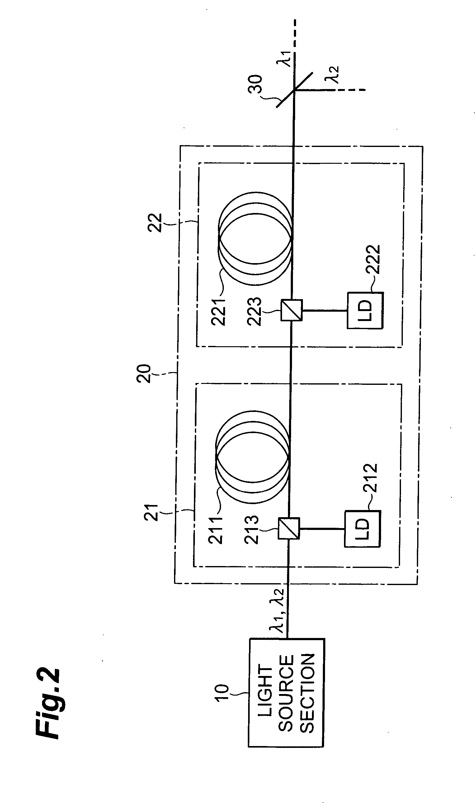
[0031]FIG. 1 shows a configuration diagram of a laser light source 1 according to the present embodiment. The laser light source 1 shown in this figure is provided for processing a processing object 2 by irradiating the processing object 2 with pulse laser light, and includes light source section 10, optical amplification section 20, optical demultiplexing section 30, optical multiplexing section 40 and optical path length difference setting section 50.

[0032] The light source section 10 outputs pulse laser light having a first wavelength λ1 (hereinafter denoted as ‘pulse laser light λ1’) and pulse laser light having a second wavelength (hereinafter denoted as ‘pulse laser light λ2’) of which frequencies are rest...


PUM


Abstract

A laser light source includes a light source section for outputting pulse laser light λ1, λ2 with a mutually identical repetition frequency, an optical amplification section for amplifying and outputting the pulse laser light λ1, λ2 output from the above light source section by means of a common optical amplification medium, an optical demultiplexing section for mutually demultiplexing pulse laser light λ1, λ2, an optical multiplexing section for multiplexing and outputting the pulse laser light λ1, λ2 demultiplexed in the above optical demultiplexing section, and an optical path length difference setting section for adjusting an optical path length difference between the pulse laser light λ1, λ2 in between the optical demultiplexing section and the optical multiplexing section.

Description

BACKGROUND OF THE INVENTION [0001] 1. Field of the Invention [0002] The present invention relates to a laser light source, a laser oscillation method and a laser processing method suitable for processing use (processing, reformation, cleaning, and the like). Also, the present invention is effective for measurement of a long distance and destruction of an object to be measured which require a high output light source. [0003] 2. Related Background of the Invention [0004] The laser light source is used not only for communication but also for processing. The laser light source for processing use (in particular, microfabrication) requires large mean power of the output laser light, excellent quality M2 of the output laser light, large peak power of the output laser light, and large pulse energy of the output laser light. [0005] For example, a laser light source having been disclosed in “27-mJ nanosecond pulses in M2=6.5 beam from a coiled highly multimode Yb-doped fiber amplifier”, M.-Y ...

Claims


Application Information

Patent Timeline
Patent Type & Authority Applications(United States)
IPC IPC(8): H04J14/02
CPCH01S3/06758H01S5/005H04J14/0221H01S5/4087H04J14/02H01S5/0057
Inventor TSUCHIYA, ICHIROKAKUI, MOTOKI
Owner SUMITOMO ELECTRIC IND LTD
Why Eureka
Try Eureka