
Zero g inertia exercise apparatus
a technology of exercise apparatus and zero g inertia, which is applied in the field of exercise apparatus and method, can solve the problems of ineffective exercise to maintain muscle mass in such an environment, and achieve the effect of stimulating bone development, eliminating and/or reducing bone mass loss
- Summary
- Abstract
- Description
- Claims
- Application Information
AI Technical Summary
Benefits of technology
Problems solved by technology
Method used
Image

Examples
first embodiment
The The Rotary Platform
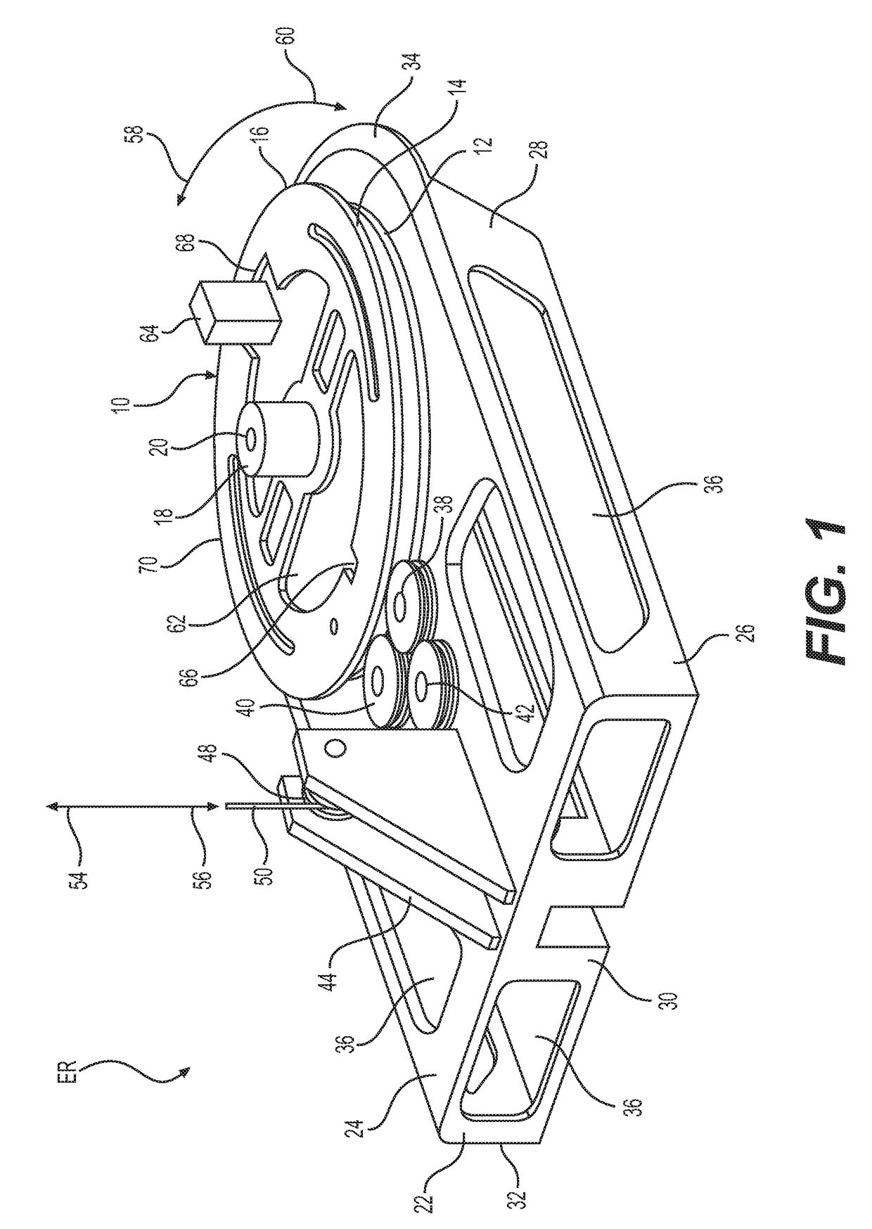
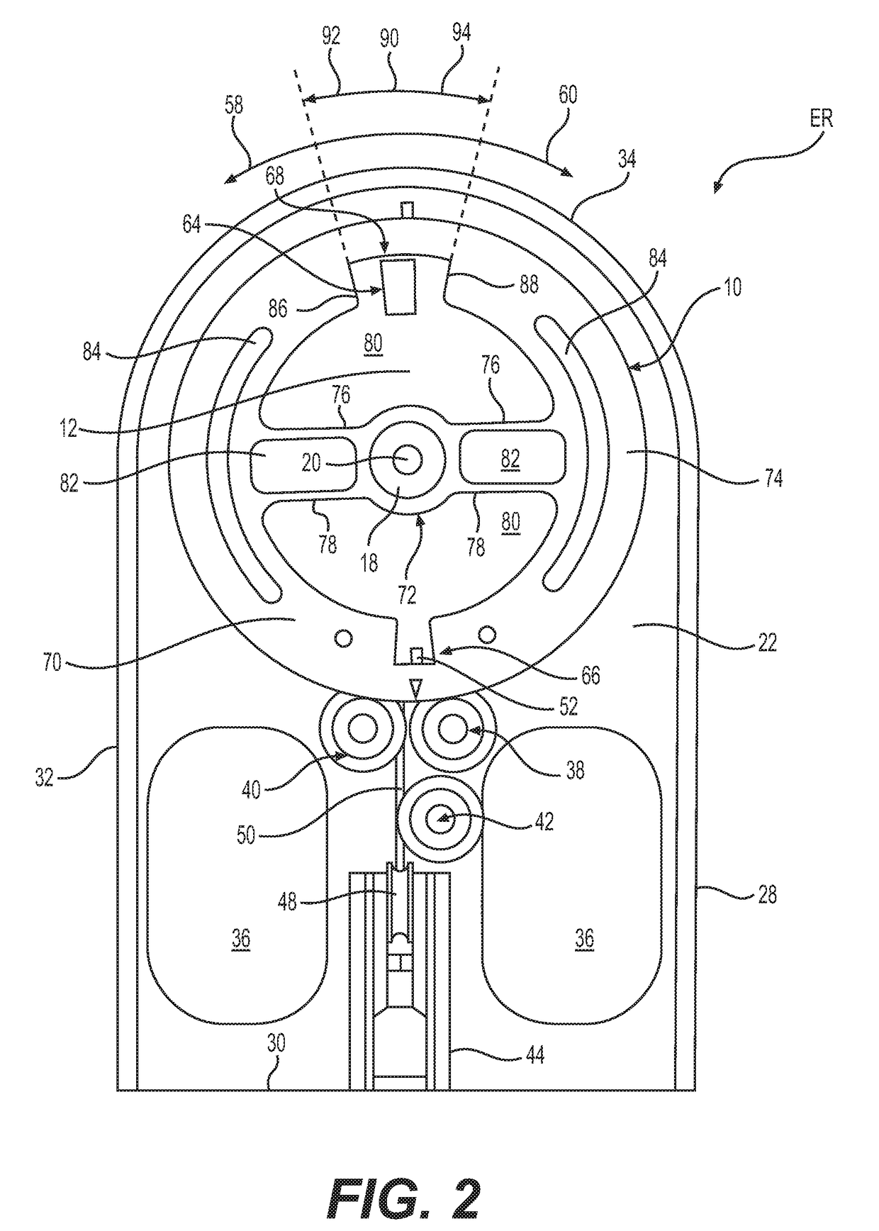
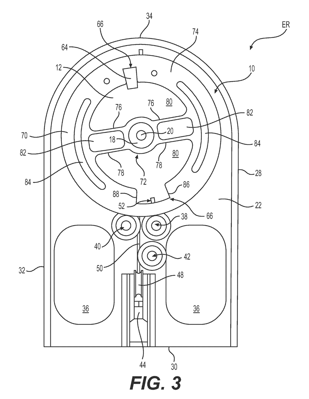
[0062]The first embodiment of a movable platform of the exerciser ER is illustrated in FIGS. 1-7.
[0063]In this first embodiment, the movable platform relies on rotary motion to generate the instantaneous force spikes. Accordingly, for this first embodiment, the movable platform is referred to as a rotary platform 10.
[0064]The rotary platform 10 encompasses a circular plate 12 with a peripheral groove 14 around its perimeter 16. The rotary platform 10 includes a hub 18 at its center. In the illustrated embodiment, the hub 18 is integrally formed with the circular plate 12. As such, the hub 18 is contemplated to rotate around a shaft 20 at the center of the hub 18. The shaft 20 is attached to a frame 22 that supports the rotary platform 10.
[0065]It is noted that the rotary platform 10 is not intended to be limited solely to the construction depicted. To the contrary, the rotary platform 10 may be constructed in any alternative manner as may be apparent to those...
second embodiment
The The Linear Platform
[0109]A second embodiment of the exerciser EL of the present invention is illustrated in FIGS. 8-15.
[0110]Aspects of elements of the exerciser ER apply equally to the exerciser EL. For example, the materials for various components apply to the equivalent components that form the exerciser EL
[0111]FIG. 8 is a perspective illustration of the exerciser EL, showing the overall construction for the exerciser EL.
[0112]According to the second embodiment of the present invention, the exerciser EL has a linear platform 110 that is slidably disposed on a frame 112. Here, the exerciser EL does not rely on rotary motion for acceleration, deceleration, and the generation of instantaneous force spikes, as discussed above in connection with the exerciser EL with the rotary platform 10.
[0113]As with the frame 22, the frame 112 may be made from any suitable material. Examples of suitable materials include, but are not limited to, lightweight materials, aluminum, aluminum allo...
PUM
 Abstract
Description
Claims
Application Information