Smoke removal device

Active Publication Date: 2020-05-28
GRAND MATE
View PDF7 Cites 0 Cited by
  • Summary
  • Abstract
  • Description
  • Claims
  • Application Information

AI Technical Summary

Benefits of technology

[0007]The advantage of the present invention is that efficiently facilitates the particulates passing through the smoke passage to be burned by the fire produced by the burner, and decreases the possibility that the fuel gas released from the gas pipeline is interfered by the air flow formed by the particulates passing through.
[0008]The present invention will be best understood by referring to the following detailed description of some illustrative embodiments in conjunction with the accompanying draw

Problems solved by technology

The smoke full of the particulates and dispersed in the air would pollute the environment.
The particulates with small volume and light mass are moved by the gas flow easily, result in increasing the possibility of the particulates being inhaled.
When being inhaled by the creature and getting into the respiratory tract of the creature, the particulates would stimulate the respiratory tract and could cause the creature to be uncomfortable, like being allergic or suffering from asthma.
Some particulates would even attach to the lung and could not be discharged which causes the creature to suffer from a more serious disea

Method used


Image

  • Smoke removal device
  • Smoke removal device
  • Smoke removal device

Examples


Example

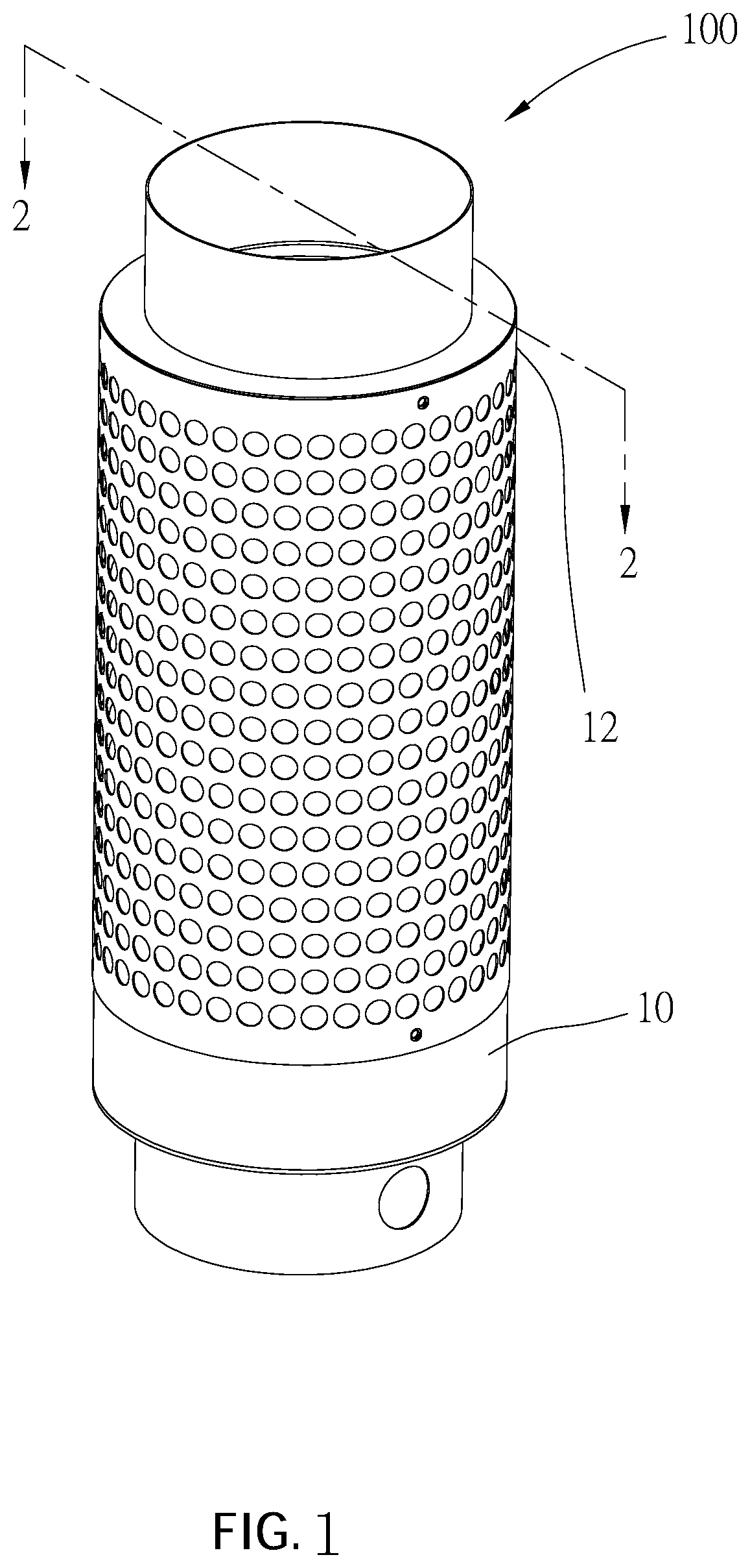
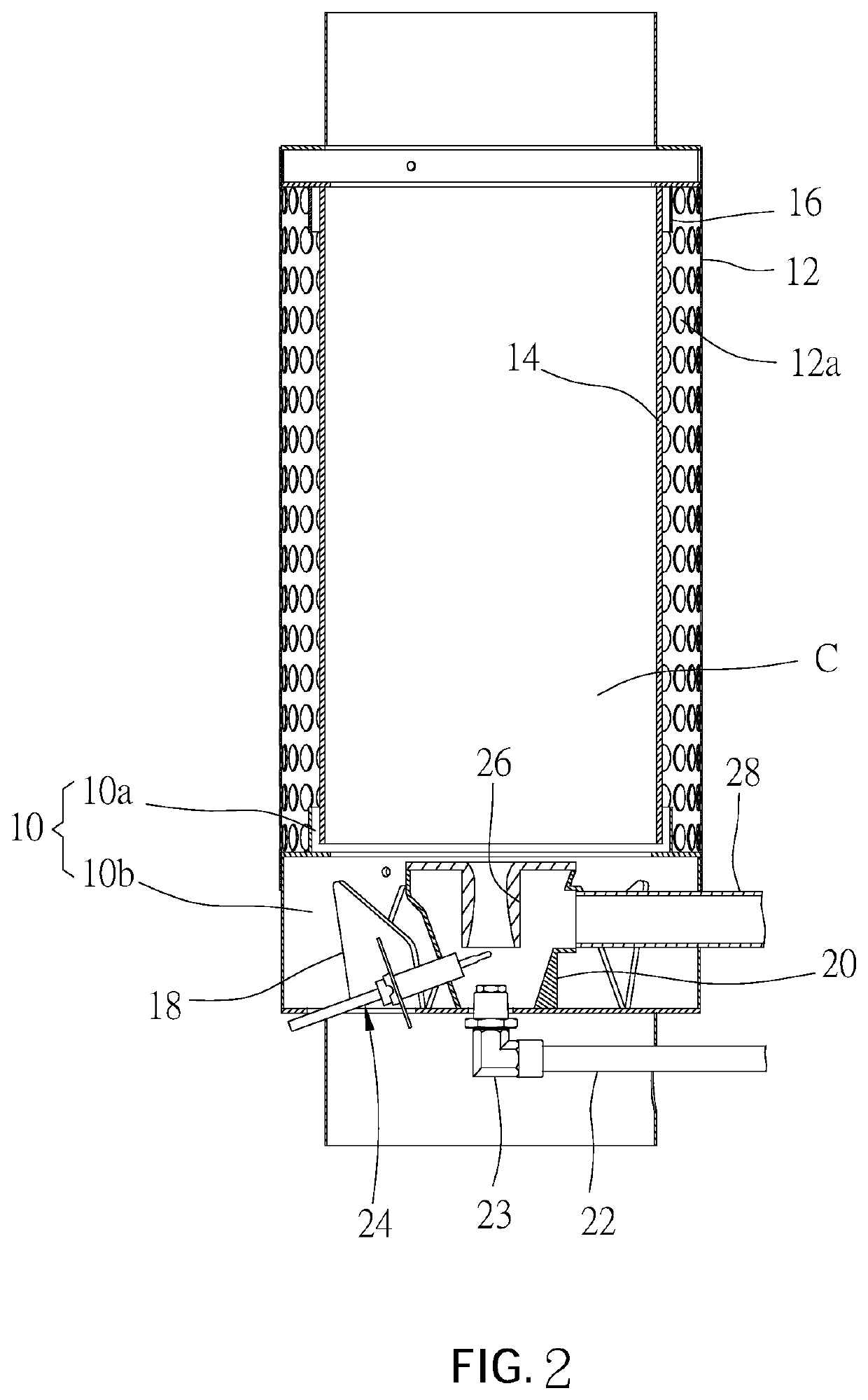
[0017]The embodiments of the smoke removal device of the present invention will be explained clearly with reference to the drawings thereafter. FIG. 1 to FIG. 4 show the smoke removal device 100 of the first embodiment.

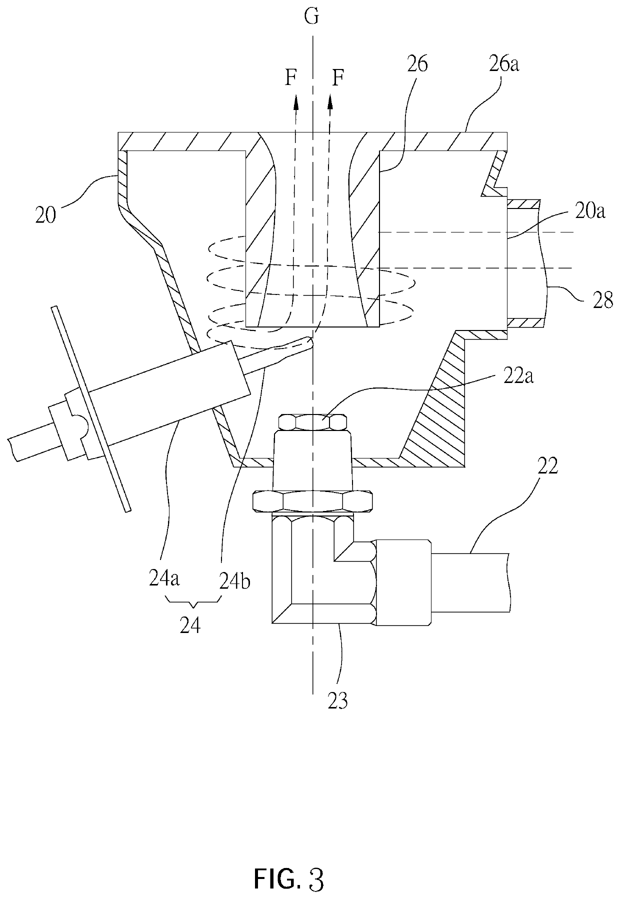
[0018]The smoke removal device 100 includes a base 10, a cylinder 12, a tube body 14, a converging tube 16, a guiding fan 18, and a combustion unit. The base 10 being a hollow structure has a fixing portion 10a and an accommodating room 10b. The fixing portion 10a is located in the cylinder 12. The cylinder 12 is mounted on the base 10 and has a plurality of heat dissipation openings 12a. A first end of the tube body 14 is connected to the fixing portion 10a of the base 10, while a second end of the tube body 14 is connected to the converging tube 16, thereby the base 10, the tube body 14 and the converging tube 16 all communicating to each other. The guiding fan 18 is provided in the accommodating room 10b of the base 10 and surrounds the combustion unit.

[0019]The co...


PUM

PropertyMeasurementUnit
Diameteraaaaaaaaaa
Lengthaaaaaaaaaa
Shapeaaaaaaaaaa

Abstract

A smoke removal device, which can burn the particulates in the smoke efficiently, includes a tube body and a combustion unit. The combustion unit is provided in the tube body and includes a main body, a gas pipeline, and a lighter. The main body is located at a first end of the tube body. A smoke passage is formed between a periphery of the main body and an inner wall of the tube body, and the smoke enters the smoke removal device through the smoke passage. The main body has a central passage therethrough, where a fuel gas is ignited. The fuel gas is guided to the central passage through the gas pipeline and then ignited by the lighter to burn the smoke particulates passing through the smoke passage.

Description

BACKGROUND OF THE INVENTIONTechnical Field[0001]The present invention is related to a burner and, more particularly, to a smoke removal device, which is used to efficiently burn the particulates in the smoke.Description of Related Art[0002]Conventional combustion devices (e.g., furnaces, gold furnaces, or coffee bean roasters) generate particulates during combustion of the material, and the thermal energy provided by the combustion device changes the density of the air, thereby generating a gas flow and forming the smoke full of the particulates. Finally, the particulates are discharged outside the combustion device with the smoke and dispersed in the air.[0003]The smoke full of the particulates and dispersed in the air would pollute the environment. The particulates with small volume and light mass are moved by the gas flow easily, result in increasing the possibility of the particulates being inhaled. When being inhaled by the creature and getting into the respiratory tract of the...

Claims


Application Information

Patent Timeline
IPC IPC(8): F23G7/06B01D46/24F23J15/02
CPCB01D46/2403F23G7/065F23J15/022F23D2900/14241F23D2900/21003F23J15/08F23J2900/15081
Inventor HUANG, CHUNG-CHINHUANG, CHIN-YINGHUANG, HSIN-MINGHUANG, HSING-HSIUNGYEH, YEN-JENLIN, KUAN-CHOU
Owner GRAND MATE
Why Eureka
Try Eureka